Installazione della cpu, Diagramma disposizione scheda madre, Italiano – Asus P5LD2-VM User Manual
Page 8: Pentium
8
A S U S P 5 L D 2 - V M
A S U S P 5 L D 2 - V M
A S U S P 5 L D 2 - V M
A S U S P 5 L D 2 - V M
A S U S P 5 L D 2 - V M
Italiano
2.
Installazione della CPU
Attenersi alle seguenti fasi per installare un processore Intel
®
Pentium
®
4
nel pacchetto 775.
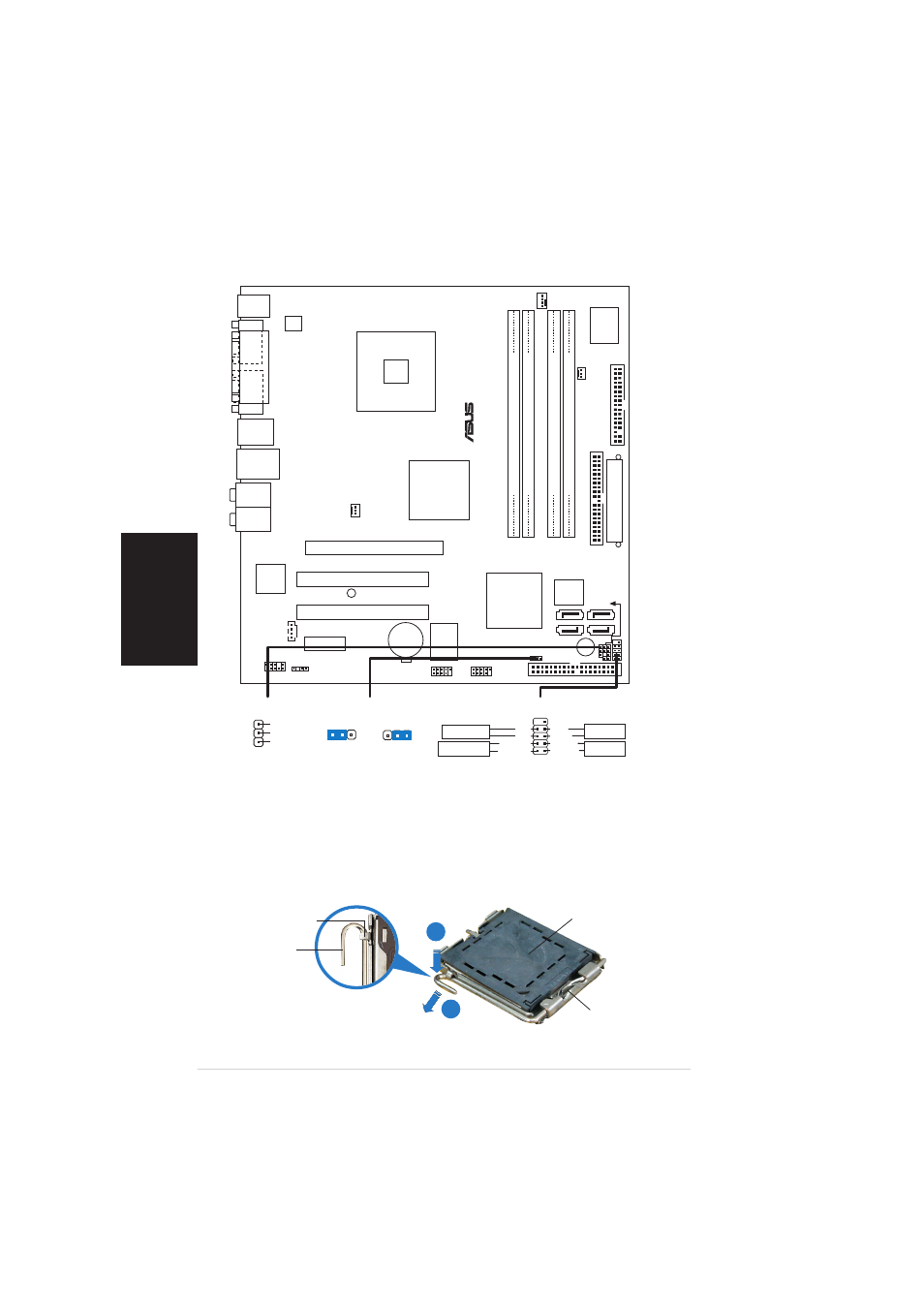
1.
Premere la levetta di carico con il pollice (A), poi spostarla e sinistra
(B) finché è liberata dalla linguetta di trattenimento.
1.
Diagramma disposizione scheda madre
L i n g u e t t a d i
L i n g u e t t a d i
L i n g u e t t a d i
L i n g u e t t a d i
L i n g u e t t a d i
t r a t t e n i m e n t o
t r a t t e n i m e n t o
t r a t t e n i m e n t o
t r a t t e n i m e n t o
t r a t t e n i m e n t o
L e v e t t a d i
L e v e t t a d i
L e v e t t a d i
L e v e t t a d i
L e v e t t a d i
c a r i c o
c a r i c o
c a r i c o
c a r i c o
c a r i c o
Q u e s t o l a t o d e l m o d u l o
Q u e s t o l a t o d e l m o d u l o
Q u e s t o l a t o d e l m o d u l o
Q u e s t o l a t o d e l m o d u l o
Q u e s t o l a t o d e l m o d u l o
d e v e e s s e r e r i v o l t o
d e v e e s s e r e r i v o l t o
d e v e e s s e r e r i v o l t o
d e v e e s s e r e r i v o l t o
d e v e e s s e r e r i v o l t o
v e r s o s é s t e s s i .
v e r s o s é s t e s s i .
v e r s o s é s t e s s i .
v e r s o s é s t e s s i .
v e r s o s é s t e s s i .
C o p e r t u r a P n P
C o p e r t u r a P n P
C o p e r t u r a P n P
C o p e r t u r a P n P
C o p e r t u r a P n P
A
B
Below:
Center/Subwoofer
Center:
Side Speaker Out
Top:Rear Speaker Out
CR2032 3V
Lithium Cell
CMOS Power
CD
Super
I/O
Intel FWH
4Mb
ATX12V
FLOPPY
AAFP
DDR DIMM_A1 (64 bit,240-pin module)
SB_PWR
F_P
ANEL
CHASSIS
USB78
USB56
CLRTC
PCI1
Intel
®
GMCH
945G
Intel
®
ICH7
DDR DIMM_A2 (64 bit,240-pin module)
DDR DIMM_B1 (64 bit,240-pin module)
DDR DIMM_B2 (64 bit,240-pin module)
CHA_FAN
CPU_FAN
PRI_IDE
EA
TXPWR
PCI2
SPDIF_OUT
Intel
82573V
LGA775
PS/2KBMS
T: Mouse
B: Keyboard
Below:Mic In
Center:Line Out
Top:Line In
F_USB12
LAN_USB34
PCIEX1_1
PCIEX16
COM1
P
ARALLEL
POR
T
VGA1
PLED
®
P5LD2-VM
ITE 821
1
SATA1
SATA2
SATA4
SATA3
BUZZ
PWR_F
AN
PCI_EIDE
SPEAKER
F_PANEL
*
Requires an ATX power supply.
PWR
Ground
GND
Reset
IDE_LED+
IDE_LED-
RESET
IDE LED
PWRSW
PWR_LED-
PWRLED
PWR_LED+
CLRTC
Normal
Clear CMOS
(Default)
1 2
2 3
PLED
PLED+
1
NC
PLED-