2 internal connectors – Asus M2N68-VM User Manual
Page 36
1-24
Chapter 1: Product introduction
15. Optical S/PDIF Out port. This port connects an external audio output device
via an optical S/PDIF cable.
16. USB 2.0 ports 5 and 6. These two 4-pin Universal Serial Bus (USB) ports
are available for connecting USB 2.0 devices.
1.10.2 Internal connectors
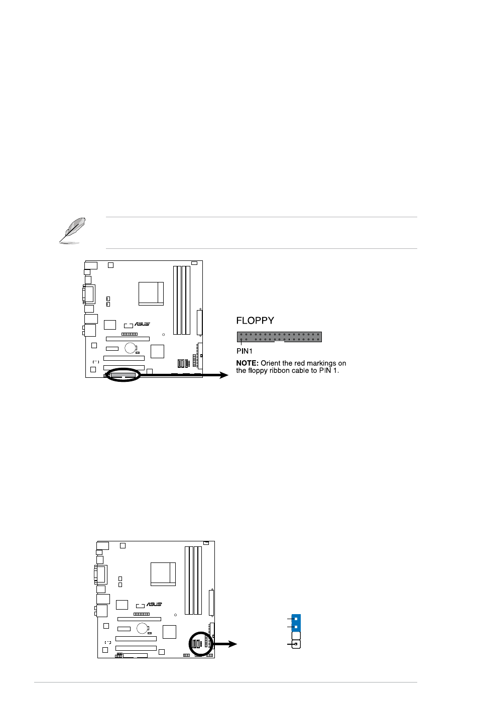
1. Floppy disk drive connector (34-1 pin FLOPPY)
This connector is for the provided floppy disk drive (FDD) signal cable. Insert
one end of the cable to this connector, then connect the other end to the
signal connector at the back of the floppy disk drive.
M2N68-VM
M2N68-VM
Floppy Disk Drive Connector
Pin 5 on the connector is removed to prevent incorrect cable connection when
using an FDD cable with a covered Pin 5.
2. Chassis intrusion connector (4-1 pin CHASSIS)
This connector is for a chassis-mounted intrusion detection sensor or switch.
Connect one end of the chassis intrusion sensor or switch cable to this
connector. The chassis intrusion sensor or switch sends a high-level signal to
this connector when a chassis component is removed or replaced. The signal
is then generated as a chassis intrusion event.
By default, the pins labeled “Chassis Signal” and “Ground” are shorted with
a jumper cap. Remove the jumper caps only when you intend to use the
chassis intrusion detection feature.
M2N68-VM
M2N68-VM Intrusion Connector
CHASSIS
+5VSB_MB
Chassis Signal
GND
(Default)