Chapter 2, 16 chapter 2: hardware information – Asus P6X58-E PRO User Manual
Page 36
2-16
Chapter 2: Hardware information
Chapter 2
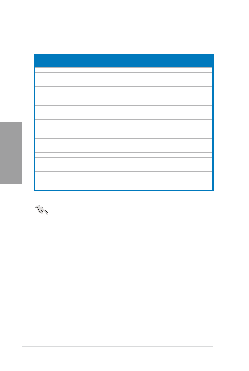
P6X58-E PRO Motherboard Qualified Vendors Lists (QVL)
DDR3-1067 MHz capability
Vendors
Part No.
Size
SS/
DS
Chip Brand Chip NO.
Timing
Voltage
DIMM socket
support (Optional)
2
3
4
6
Crucial
CT12864BA1067.8FF
1GB
SS MICRON
D9KPT
7
-
•
•
•
Crucial
CT12864BA1067.8SFD
1GB
SS MICRON
D9JNL
7
-
•
•
•
Crucial
CT12872BA1067.9FF
1GB
SS MICRON
D9KPT(ECC)
7
-
•
•
Crucial
CT25664BA1067.16FF
2GB
DS MICRON
D9KPT
7
-
•
•
•
Crucial
CT25664BA1067.16SFD
2GB
DS MICRON
D9JNL
7
-
•
•
•
•
Crucial
CT25672BA1067.18FF
2GB
DS MICRON
D9KPT(ECC)
7
-
•
•
•
•
ELPIDA
EBJ10UE8BAW0-AE-E
1GB
SS ELPIDA
J1108BABG-DJ-E
7
-
•
•
•
ELPIDA
EBJ10UE8EDF0-AE-F
1GB
SS ELPIDA
J1108EDSE-DJ-F
-
-
•
•
•
ELPIDA
EBJ21UE8BAW0-AE-E
2GB
DS ELPIDA
J1108BABG-DJ-E
7
-
•
•
•
•
ELPIDA
EBJ21UE8EDF0-AE-F
2GB
DS ELPIDA
J1108EDSE-DJ-F
-
-
•
•
•
GEIL
GG34GB1066C8DC
4GB ( 2x 2GB ) DS GEIL
GL1L128M88BA115FW 8-8-8-20 1.3
•
•
•
•
Hynix
HMT112U6AFP8C-G7N0 1GB
SS HYNIX
H5TQ1G83AFPG7C
7
-
•
•
•
•
Hynix
HYMT112U64ZNF8-G7
1GB
SS HYNIX
HY5TQ1G831ZNFP-G7 7
-
•
•
Hynix
HMT125U6AFP8C-G7N0 2GB
DS HYNIX
H5TQ1G83AFPG7C
7
-
•
•
•
•
Hynix
HYMT125U64ZNF8-G7
2GB
DS HYNIX
HY5TQ1G831ZNFP-G7 7
-
•
•
•
Kingston
KVR1066D3N7/1G
1GB
SS Kingston
D1288JPNDPLD9U
7
1.5
•
•
•
•
Kingston
KVR1066D3N7/2G
2GB
DS Elpida
J1108BDSE-DJ-F
7
1.5
•
•
•
KINGSTON KVR1066D3N7K2/4G
4GB ( 2x 2GB ) DS KINGSTON D1288JELDNGD9U
-
1.5
•
•
•
•
MICRON
MT8JTF12864AZ-1G1F1 1GB
SS MICRON
8ZF22 D9KPV
7
-
•
•
•
MICRON
MT8JTF12864AZ-1G1F1 1GB
SS MICRON
D9KPT
7
-
•
•
•
MICRON
MT16JTF25664AZ-1G1F1 2GB
DS MICRON
8ZF22 D9KPV
7
-
•
•
•
MICRON
MT16JTF25664AZ-1G1F1 2GB
DS MICRON
D9KPT
7
-
•
•
•
SAMSUNG M378B5273BH1-CF8
4GB
DS SAMSUNG K4B2G0846B-HCF8
8
1.5
•
•
•
Elixir
M2Y2G64CB8HC5N-BE
2GB
DS Elixir
N2CB1G80CN-BE
-
-
•
•
•
Elixir
M2Y2G64CB8HC9N-BE
2GB
DS -
-
-
-
•
•
•
•
WINTEC
3DU3191A-10
1GB
DS Qimonda
IDSH51-03A1F1C-10F 7
-
•
•
•
6 DIMM Slots
•
2 DIMM: Supports two (2) modules inserted into slot A1 and B1 as one pair of Dual-
channel memory configuration
•
3 DIMM: Supports three (3) modules inserted into the orange slots (A1, B1 and C1) as
one set of Triple-channel memory configuration
•
4 DIMM: Supports four (4) modules inserted into the orange slots (A1, B1 and C1) and
the black slot A2 as one set of Triple-channel memory configuration
•
6 DIMM: Supports six (6) modules inserted into both the orange slots and the black
slots as two set of Triple-channel memory configuration.
•
When installing total memory of 4GB capacity or more, Windows 32-bit operation
system may only recognize less than 3GB. Hence, a total installed memory of less
than 3GB is recommended.
•
It is recommended to install the memory modules from the slots for better overclocking
capability.
•
The default DIMM frequency depends on its Serial Presence Detect (SPD), which is
the standard way of accessing information from a memory module. Under the default
state, some memory modules for overclocking may operate at a lower frequency than
the vendor-marked value.