3 motherboard layout, 4 layout contents, Motherboard layout -6 – Asus M4N78 SE User Manual
Page 16: Layout contents -6
1-6
Chapter 1: Product introduction
1.5.3
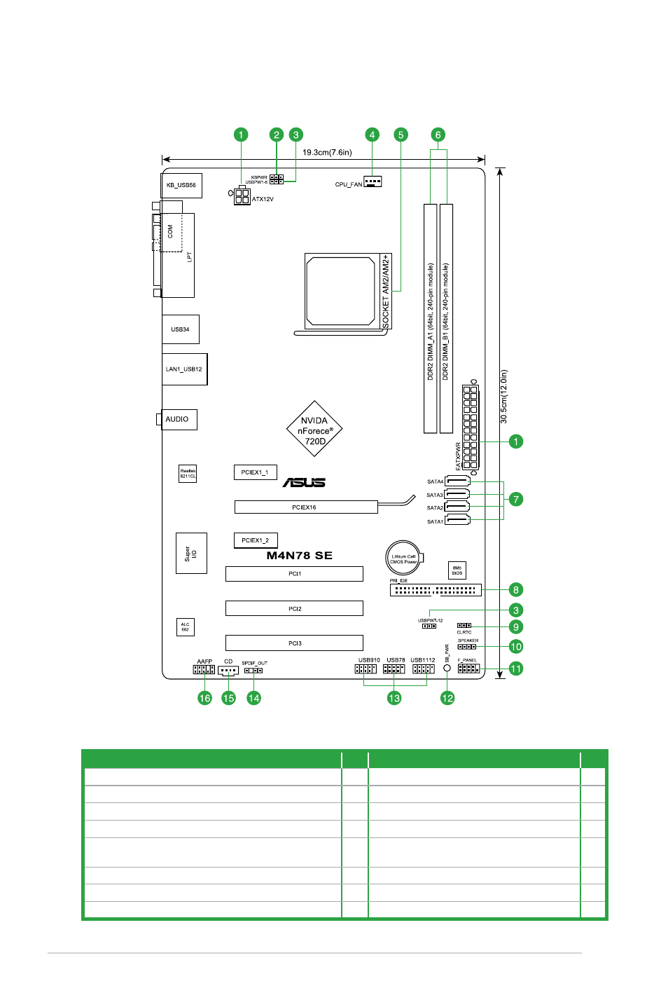
Motherboard layout
Connectors/Jumpers/Slots
Page Connectors/Jumpers/Slots
Page
1. ATX power connectors (24-pin EATXPWR, 4-pin ATX12V)
1-21 9. Clear RTC RAM (3-pin CLRTC)
1-18
2. Keyboard power (3-pin KBPWR)
1-19 10. Speaker (4-pin SPEAKER)
1-24
3. USB device wake-up (3-pin USBPW1-6, USBPW7-12)
1-19 11. System panel connector (10-1 pin F_PANEL)
1-24
4. CPU fan connector (4-pin CPU_FAN)
1-8 12. Onboard LED
1-4
5. AM2/AM2+ CPU socket
1-7 13. USB connectors (10-1 pin USB78, USB910,
USB1112)
1-25
6. DDR2 DIMM slots
1-10 14. Digital audio connector (4-1 pin SPDIF_OUT)
1-22
7. Serial ATA connectors (7-pin SATA1, SATA2, SATA3, SATA4) 1-23 15.Optical drive audio in connector (4-pin CD)
1-23
8. IDE connector (40-1 pin PRI_IDE)
1-22 16. Front panel audio connector (10-1 pin AAFP)
1-25
1.5.4
Layout contents