Setting 1: using single-channel scsi/raid card – Asus AP1710-E1 User Manual
Page 60
C h a p t e r 2 : H a r d w a r e s e t u p
C h a p t e r 2 : H a r d w a r e s e t u p
C h a p t e r 2 : H a r d w a r e s e t u p
C h a p t e r 2 : H a r d w a r e s e t u p
C h a p t e r 2 : H a r d w a r e s e t u p
2 - 3 6
2 - 3 6
2 - 3 6
2 - 3 6
2 - 3 6
Refer to the following tables for the jumper settings and the appropriate
ID# for each SCSI HDD bay.
C a s c a d e c o n f i g u r a t i o n
C a s c a d e c o n f i g u r a t i o n
C a s c a d e c o n f i g u r a t i o n
C a s c a d e c o n f i g u r a t i o n
C a s c a d e c o n f i g u r a t i o n
F i r s t b a c k p l a n e ( B P 1 )
F i r s t b a c k p l a n e ( B P 1 )
F i r s t b a c k p l a n e ( B P 1 )
F i r s t b a c k p l a n e ( B P 1 )
F i r s t b a c k p l a n e ( B P 1 )
J 1 s e t t i n g
J 1 s e t t i n g
J 1 s e t t i n g
J 1 s e t t i n g
J 1 s e t t i n g
(1-3 shorted, 2-4 shorted)
D e v i c e
D e v i c e
D e v i c e
D e v i c e
D e v i c e
S C S I I D #
S C S I I D #
S C S I I D #
S C S I I D #
S C S I I D #
Drive Bay 1
ID0
Drive Bay 2
ID1
Drive Bay 3
ID2
Drive Bay 4
ID3
GEM SAF-TE
ID15
S e c o n d b a c k p l a n e ( B P 2 )
S e c o n d b a c k p l a n e ( B P 2 )
S e c o n d b a c k p l a n e ( B P 2 )
S e c o n d b a c k p l a n e ( B P 2 )
S e c o n d b a c k p l a n e ( B P 2 )
J 1 s e t t i n g
J 1 s e t t i n g
J 1 s e t t i n g
J 1 s e t t i n g
J 1 s e t t i n g
(3-5 shorted, 4-6 shorted)
D e v i c e
D e v i c e
D e v i c e
D e v i c e
D e v i c e
S C S I I D #
S C S I I D #
S C S I I D #
S C S I I D #
S C S I I D #
Drive Bay 5
ID4
Drive Bay 6
ID5
Drive Bay 7
ID6
Drive Bay 8
ID8
GEM SAF-TE
ID11
Setting 1: Using single-channel SCSI/RAID card
SCSI backplane jumper settings and HDD ID assignments
SCSI backplane jumper settings and HDD ID assignments
SCSI backplane jumper settings and HDD ID assignments
SCSI backplane jumper settings and HDD ID assignments
SCSI backplane jumper settings and HDD ID assignments
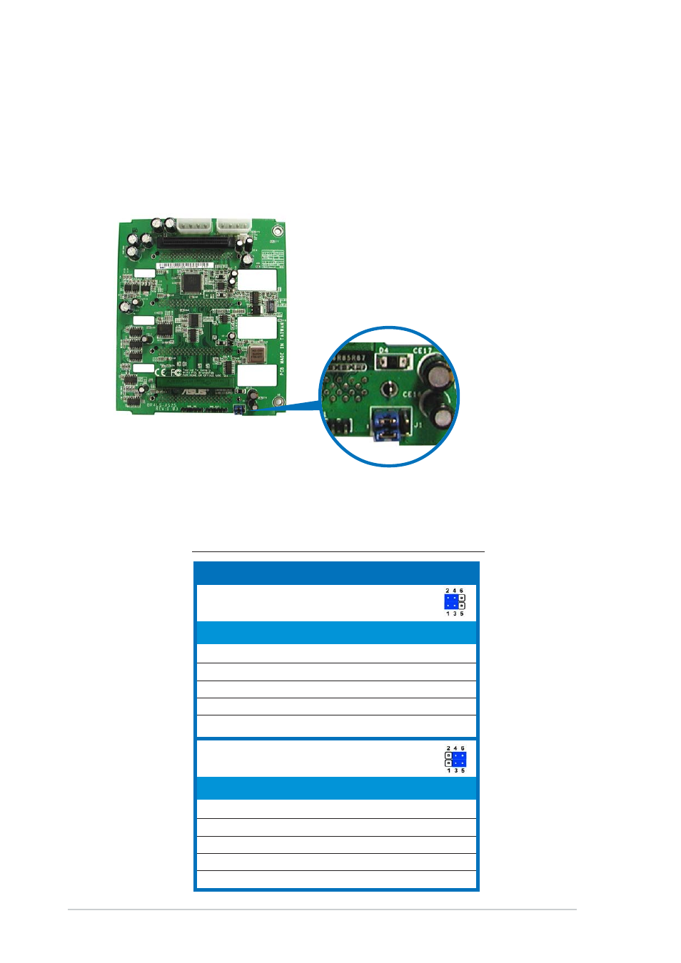
The 6-pin jumper J 1
J 1
J 1
J 1
J 1 on each of the SCSI backplanes allows you to define
your desired SCSI configuration.
The picture below shows the location of jumper J1 with pins 1-3 and 2-4
shorted.