5 asus q-connector (system panel), Asus q-connector (system panel) -33 – Asus ESC1000 G2 User Manual
Page 81
ASUS ESC1000 G2
3-33
3.5.5
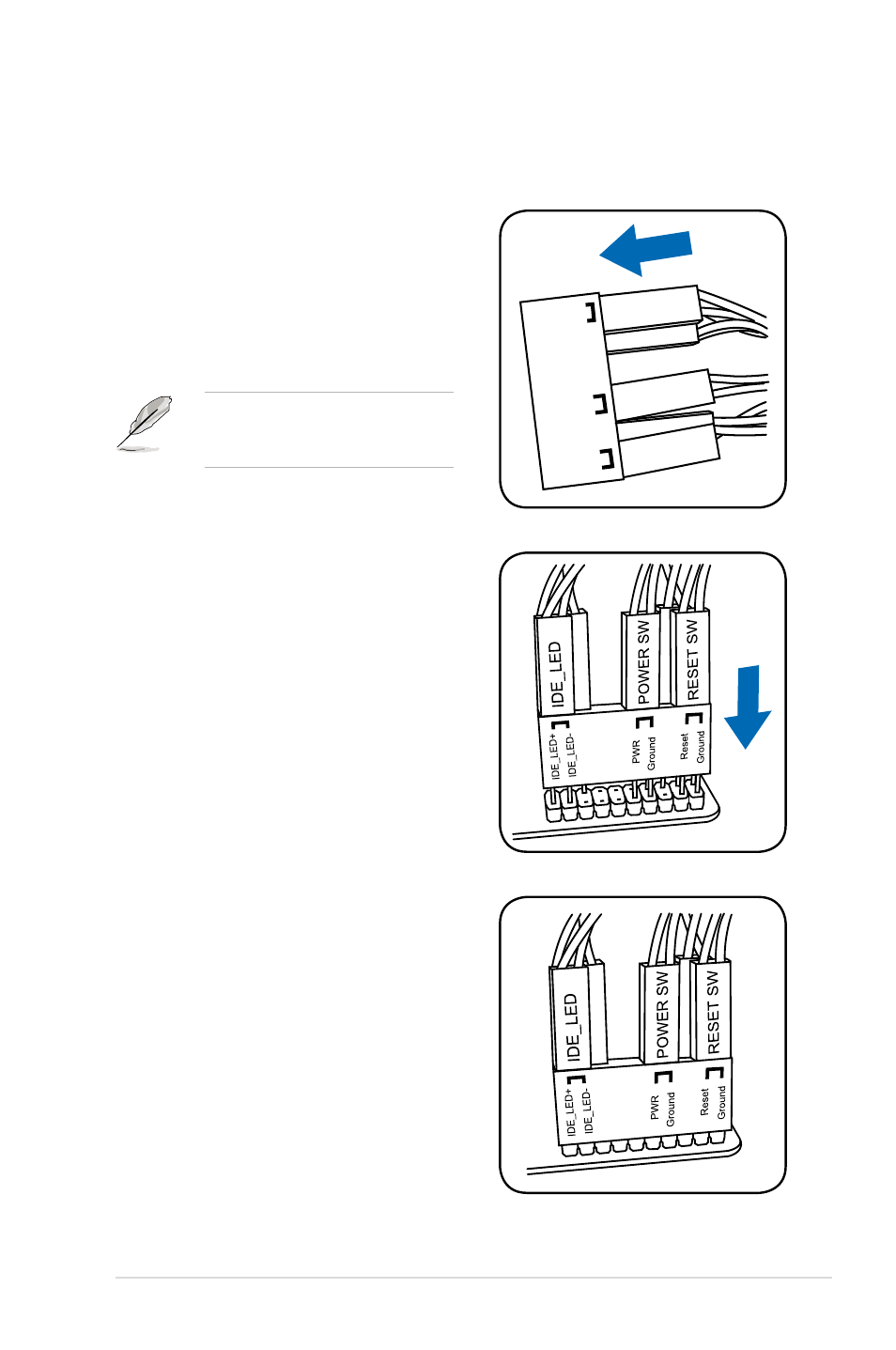
ASUS Q-Connector (system panel)
Use the ASUS Q-Connector to connect/disconnect the chassis front panel cables.
1.
Connect the front panel cables to the ASUS
Q-Connector.
Refer to the labels on the Q-Connector to
know the detailed pin definitions, and then
match them to their respective front panel
cable labels.
The labels on the front panel cables
may vary depending on the chassis
model.
IDE_LED
POWER SW
RESET SW
IDE_LED-
IDE_LED+
PWR
Reset
Ground
Ground
2.
Install the ASUS Q-Connector to the system
panel connector, ensuring the orientation
matches the labels on the motherboard.
3.
The front panel functions are now enabled.
The figure shows the
Q-Connector is properly installed on the
motherboard.
See also other documents in the category Asus Computer hardware:
- AP2500 (40 pages)
- AP1700-S5 (58 pages)
- RS700-E6/ERS4 (138 pages)
- AP1600R-E2(AA2) (150 pages)
- P7F-E (162 pages)
- RS161-E4/PA2 (126 pages)
- RS163-E4/RX4 (11 pages)
- M2N-LR (113 pages)
- P5BV/SAS (184 pages)
- K8N-DRE (142 pages)
- RS161-E5/PA2 (124 pages)
- LSI SAS3442X-R (68 pages)
- ESC4000/FDR G2 (200 pages)
- PIKE 2208 (16 pages)
- ESC4000 (162 pages)
- ESC4000 (22 pages)
- PSCH-SR/IDE (102 pages)
- P9D-M (156 pages)
- RS740-E7-RS24-EG (212 pages)
- P5M2-E/4L (12 pages)
- ESC2000 G2 (226 pages)
- TS700-E6/RS8 (166 pages)
- RS160-E3/PS4 (140 pages)
- PU-DLS (134 pages)
- TR-DLSR (100 pages)
- P5BV-C/2L (161 pages)
- TS100-E5/PI4 (166 pages)
- ESC1000 Personal SuperComputer (184 pages)
- NRL-LS (120 pages)
- PCI-DA2200 (369 pages)
- P8C WS (140 pages)
- RS120-E4/PA4 (174 pages)
- P5MT-M (150 pages)
- TS Mini (114 pages)
- TS Mini (2 pages)
- TS Mini (112 pages)
- P5MT-MX/C (156 pages)
- AP140R-E1 (52 pages)
- AP140R-E1 (132 pages)
- ASMB6-iKVM (114 pages)
- DSBF-D16 (202 pages)
- DSBF-D16/SAS (200 pages)
- RS160-E5 (164 pages)
- Z8PE-D12X (170 pages)
- Z8PE-D12X (168 pages)