Iii. hardware setup, Asus p5s-vm user’s manual 27 – Asus P5S-VM User Manual
Page 27
ASUS P5S-VM User’s Manual
27
III. HARDWARE SETUP
Connectors
III. H/W SETUP
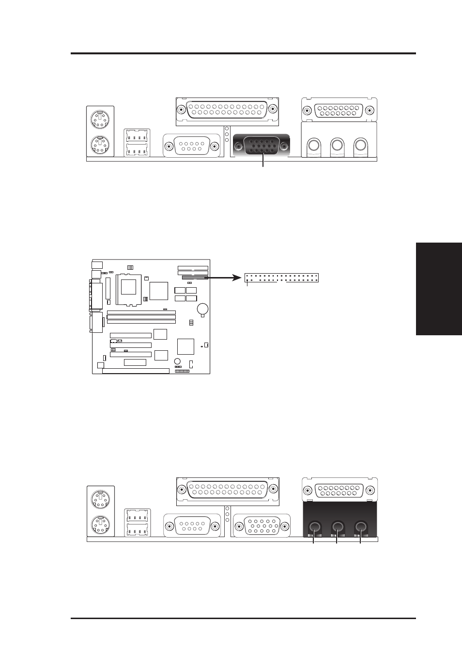
6. Monitor (VGA) Output Connector (15-pin Female)
This connector is for output to a VGA-compatible device.
VGA Monitor (15-pin Female)
7. Floppy drive connector (FLOPPY, 34-1 pin block )
This connector supports the provided floppy drive ribbon cable. After connect-
ing the single end to the board, connect the two plugs on the other end to the
floppy drives. (Pin 5 is removed to prevent inserting in the wrong orienta-
tion when using ribbon cables with pin 5 plugged).
PIN 1
P5S-VM Floppy Disk Drive Connector
NOTE: Orient the red markings on
the floppy ribbon cable to
PIN 1
0
1
8. Audio Port Connectors (Three 1/8” Female) (with optional onboard audio)
Line Out can be connected to headphones or preferably powered speakers.
Line In allows tape players or other audio sources to be recorded by your com-
puter or played through the Line Out. Mic allows microphones to be connected
for inputing voice.
Mic
Line In
Line Out
1/8" Stereo Audio Connectors