Hardware setup – Asus P4T-EM User Manual
Page 36
36
ASUS P4T-EM User’s Manual
Connectors
3. H/W SETUP
3. HARDWARE SETUP
®
P4T-EM
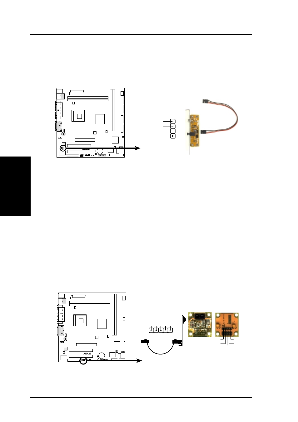
P4T-EM Infrared Module Connector
Front View
Back View
+5V
IRTX
IRRX
(NC)
GND
+5V
IRRX
IR
TX
(NC)
GND
IR
1
15) Standard and Consumer Infrared (SIR) Module Connector (5-pin IR)
This connector supports an optional wireless transmitting and receiving infrared
module. This module mounts to a small opening on system cases that support
this feature. You must also configure the setting through UART2 Use Infrared
(see 4.4.2 I/O Device Configuration) to select whether UART2 is directed for
use with COM2 or IrDA. Use the five pins as shown in Back View and connect
a ribbon cable from the module to the motherboard’s SIR connector according
to the pin definitions.
14) Digital Audio Connector (4-1 pin SPDIFOUT) (optional)
This connector supports an SPDIF audio module that processes digital instead
of analog audio output. Connect one end of the audio cable to the SPDIFOUT
connector on the motherboard and the other end to the SPDIF module. NOTE:
The SPDIF module must be purchased separately.
®
P4T-EM
P4T-EM Digital Audio Connector
+5V
SPDIFOUT
GND
SPDIFOUT