Iii. hardware setup, Asus p2z user’s manual 31 – Asus P2Z User Manual
Page 31
ASUS P2Z User’s Manual
31
III. HARDWARE SETUP
Connectors
III. H/W SETUP
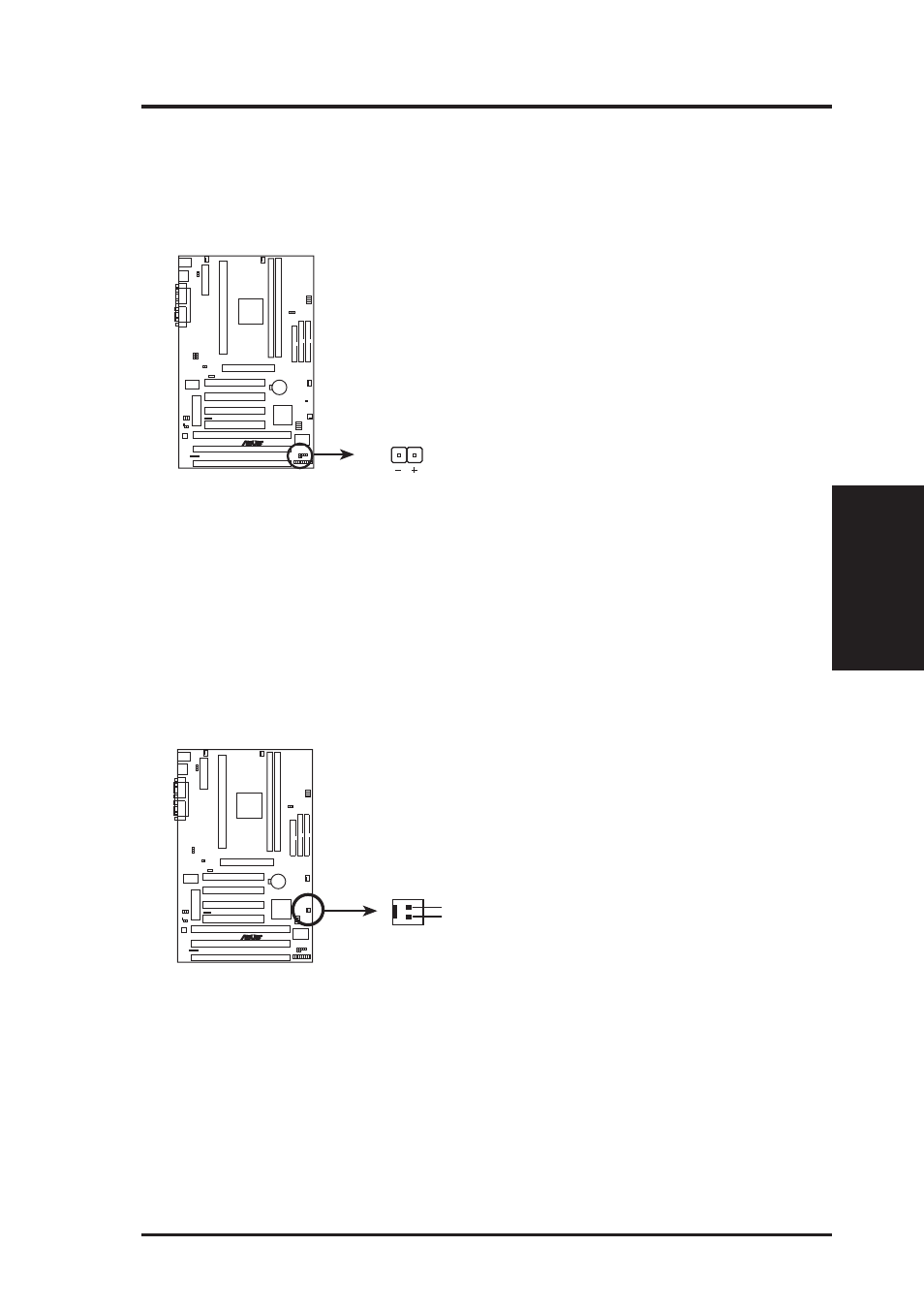
8. IDE Device Activity LED (2-pin IDELED)
This connector supplies power to the cabinet’s IDE device activity LED. Read
and write activity by devices connected to the Primary or Secondary IDE con-
nectors will cause the LED to light up.
P2Z IDE Activity LED
TIP: If the case-mounted LED does not light,
try reversing the 2-pin plug.
R
P2Z
IDELED
9. Wake-On-Ring Header (2-pin WOR)
This connector connects to internal modem cards with a Wake-On-Ring output.
The connector powers up the system when a ringup packet or signal is received
through the internal modem card. NOTE: For external modems, Wake-On-Ring
is detected through the COM port.
IMPORTANT:
This feature requires that the PWR UP On Modem Act Power
Up Control is set to Enabled (see Power Management Setup under BIOS SETUP).
P2Z Wake-On-Ring Connector
R
P2Z
WOR
Pin 2 PIXRI#
Pin 1 Ground
- P5B Premium Vista Edition (188 pages)
- P5B (140 pages)
- P5B (56 pages)
- M2N68-CM (28 pages)
- P5KPL-VM/1394/SI (94 pages)
- P5GD1-VM (92 pages)
- P5AD2-E Premium (2 pages)
- P5GD1-VM (88 pages)
- P5AD2 Premium (8 pages)
- DELUXE A7N8X-E (114 pages)
- P5KPL-AM SE (40 pages)
- P5KPL-AM SE (38 pages)
- P5KPL-AM SE (62 pages)
- P4S8X-X (64 pages)
- P5K-VM (98 pages)
- K8V-X SE (82 pages)
- M2N68-AM SE2 (40 pages)
- P4P800 SE (125 pages)
- P4P800 SE (16 pages)
- DELUXE SERIES M3A32-MVP (176 pages)
- P5AD2 Deluxe (148 pages)
- M4A79 Deluxe (122 pages)
- A7V266-E (108 pages)
- Application Manual (11 pages)
- Application Manual (10 pages)
- Application Manual (4 pages)
- Application Manual (8 pages)
- Application Manual (2 pages)
- Application Manual (6 pages)
- Application Manual (9 pages)
- Application Manual (3 pages)
- Application Manual (1 page)
- Application Manual (5 pages)
- M4A88T-I DELUXE (70 pages)
- M4A88T-I DELUXE (44 pages)
- P9X79 DELUXE (2 pages)
- RAMPAGE IV GENE (1 page)
- P9X79 (156 pages)
- P8H61-M PLUS V3 (64 pages)
- A85XM-A (78 pages)
- M4A78L-M LE (64 pages)
- M2N68-AM (96 pages)
- M2N68-AM (62 pages)
- M2N68-AM (38 pages)
- Blitz Formula (3 pages)