Installieren der cpu, Motherboard-layout, Deutsch – Asus P5P800S User Manual
Page 5: Folgen sie diesen schritten, um einen intel, Pentium
5
Deutsch
A S U S P 5 P 8 0 0 S
A S U S P 5 P 8 0 0 S
A S U S P 5 P 8 0 0 S
A S U S P 5 P 8 0 0 S
A S U S P 5 P 8 0 0 S
2.
Installieren der CPU
Folgen Sie diesen Schritten, um einen Intel
®
Pentium
®
4-Prozessor auf dem
LGA 775-Sockel zu installieren.
1.
Drücken Sie den Ladehebel mit Ihrem Daumen (A) und schieben ihn
nach links (B), bis er von dem Halteriegel losgelassen wird.
1.
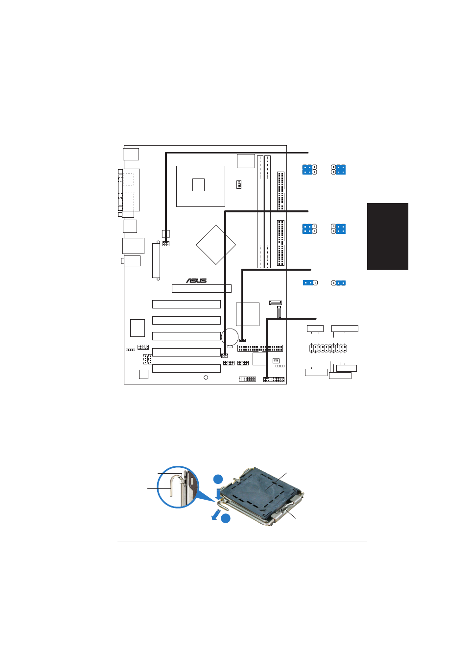
Motherboard-Layout
H a l t e r i e g e l
H a l t e r i e g e l
H a l t e r i e g e l
H a l t e r i e g e l
H a l t e r i e g e l
L a d e h e b e l
L a d e h e b e l
L a d e h e b e l
L a d e h e b e l
L a d e h e b e l
D i e s e S e i t e d e r C a m - B o x
D i e s e S e i t e d e r C a m - B o x
D i e s e S e i t e d e r C a m - B o x
D i e s e S e i t e d e r C a m - B o x
D i e s e S e i t e d e r C a m - B o x
s o l l t e z u I h n e n z e i g e n .
s o l l t e z u I h n e n z e i g e n .
s o l l t e z u I h n e n z e i g e n .
s o l l t e z u I h n e n z e i g e n .
s o l l t e z u I h n e n z e i g e n .
P n P - K a p p e
P n P - K a p p e
P n P - K a p p e
P n P - K a p p e
P n P - K a p p e
A
B
3
2
2
1
+5V
(Default)
+5VSB
USBPW78
USBPW56
3
2
2
1
+5V
(Default)
+5VSB
USBPW12
USBPW34
*
Requires an ATX power supply.
PLED-
PWR
+5V
Speaker
PLED
Ground
RESET
Ground
Reset
Ground
Ground
PLED+
IDE_LED-
IDE_LED+
IDE_LED
SPEAKER
PWRSW
PANEL
PCI1
PANEL
P5P800S
®
CD
AUX
Super
I/O
3Mb
FWH
AGP
CPU_FAN
FP_AUDIO
AD1888
GAME
CLRTC
PRI_IDE
SEC_IDE
A
TXPWR
DDR DIMM1 (64 bit,184-pin module)
CHA_FAN
Intel
ICH5
USB56
SB_PWR
USBPW78
DDR DIMM2 (64 bit,184-pin module)
USB12
PS/2KBMS
T: Mouse
B: Keyboard
SPDIF_O
P
ARALLEL
POR
T
COM1
PCI2
PCI3
PCI4
PCI5
Intel
848P
ATX12V
CR2032 3V
Lithium Cell
CMOS Power
USB78
Below:Mic In
Center:Line Out
Top:Line In
SATA1
SATA2
USBPW56
R
TL8100C
FLOPPY
USBPW12
USBPW34
CHASSIS
SPDIF_OUT
LAN_USB34
LGA775
CLRTC1
Normal
Clear CMOS
(Default)
1 2
2 3