Asus Terminator P4 533A User Manual
Page 46
46
Chapter 3: Motherboard information
2.
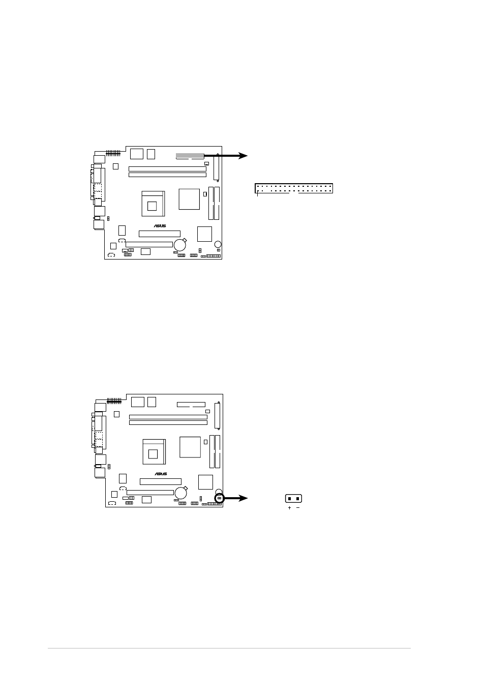
Floppy disk drive connector (34-1 pin FLOPPY1)
This connector supports the provided floppy drive ribbon cable. After
connecting one end to the motherboard, connect the other end to the
floppy drive. (Pin 5 is removed to prevent incorrect insertion when
using ribbon cables with pin 5 plug).
3.
Hard disk activity LED (2-pin IDE_LED1)
This connector supplies power to the hard disk activity LED. The read
or write activities of any device connected to the primary or
secondary IDE connector cause this LED to light up.
P4SC-EA
®
P4SC-EA Floppy Disk Drive Connector
FLOPPY1
NOTE: Orient the red markings on
the floppy ribbon cable to PIN 1.
PIN 1
P4SC-EA
®
P4SC-EA IDE Activity LED
TIP: If the case-mounted LED does not
light, try reversing the 2-pin plug.
IDE_LED1
- CG8565 (410 pages)
- CG8565 (246 pages)
- CS5111 (26 pages)
- CS5120 (1 page)
- ET1611PUK (38 pages)
- S2-P8H61E (80 pages)
- P2-PH1 (80 pages)
- P1-P5945G (80 pages)
- P2-P5945GCX (90 pages)
- CG8270 (72 pages)
- CG8270 (76 pages)
- CG8270 (534 pages)
- CG8270 (362 pages)
- CG8270 (218 pages)
- CG8270 (536 pages)
- P3-P5G31 (100 pages)
- P3-PH4 (80 pages)
- P2-M2A690G (80 pages)
- P2-M2A690G (8 pages)
- P4-P5N9300 (82 pages)
- P4-P5N9300 (1 page)
- P1-P5945GC (92 pages)
- P2-P5945GC (92 pages)
- P3-P5G33 (98 pages)
- T3-P5945GCX (80 pages)
- T3-P5945GC (80 pages)
- P2-M2A690G (94 pages)
- T3-PH1 (80 pages)
- T3-PH1 (82 pages)
- T5-P5G41E (76 pages)
- T5-P5G41E (82 pages)
- S1-AT5NM10E (68 pages)
- P6-P7H55E (67 pages)
- ES5000 (174 pages)
- T4-P5G43 (104 pages)
- T-P5G31 (92 pages)
- BT6130 (2 pages)
- BT6130 (60 pages)
- BT6130 (54 pages)
- CG8265 (350 pages)
- CG8265 (210 pages)
- CM1740 (198 pages)
- CM1740 (330 pages)
- CM1740 (70 pages)
- P6-M4A3000E (59 pages)