Asus T2-PE1 User Manual
Page 69
4 - 9
4 - 9
4 - 9
4 - 9
4 - 9
A S U S T 2 - P E 1
A S U S T 2 - P E 1
A S U S T 2 - P E 1
A S U S T 2 - P E 1
A S U S T 2 - P E 1
1 2 .
1 2 .
1 2 .
1 2 .
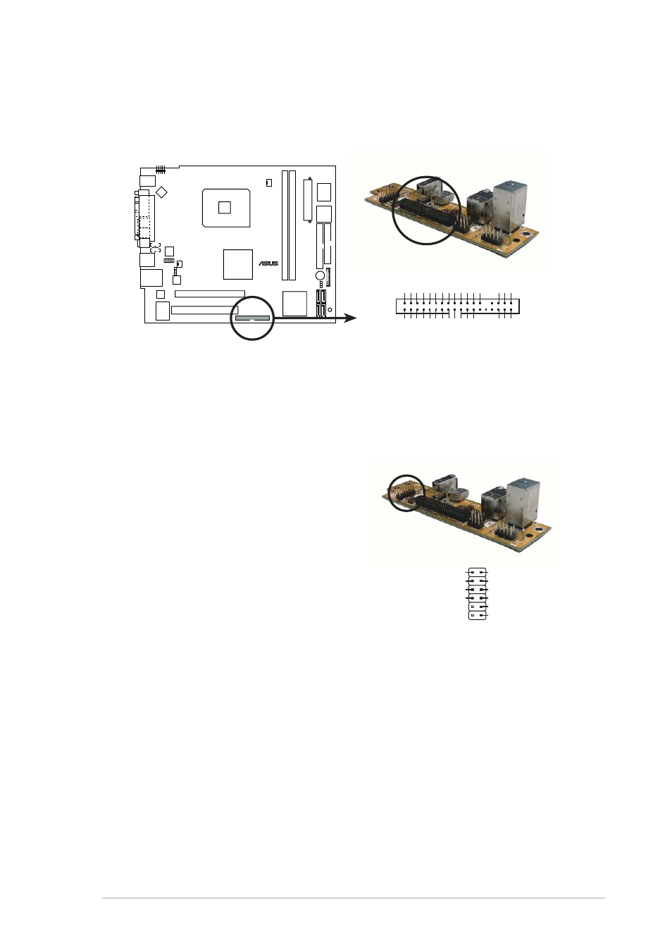
1 2 . System panel connector (8-1 pin PANEL)
S y s t e m p a n e l c o n n e c t o r ( 8 - 1 p i n P A N E L )
S y s t e m p a n e l c o n n e c t o r ( 8 - 1 p i n P A N E L )
S y s t e m p a n e l c o n n e c t o r ( 8 - 1 p i n P A N E L )
S y s t e m p a n e l c o n n e c t o r ( 8 - 1 p i n P A N E L )
This connector accommodates several system front panel functions.
•
•
•
•
•
I E E E 1 3 9 4 c o n n e c t o r s ( 5 - p i n 1 3 9 4 , 6 - p i n I E E E 1 3 9 4 )
I E E E 1 3 9 4 c o n n e c t o r s ( 5 - p i n 1 3 9 4 , 6 - p i n I E E E 1 3 9 4 )
I E E E 1 3 9 4 c o n n e c t o r s ( 5 - p i n 1 3 9 4 , 6 - p i n I E E E 1 3 9 4 )
I E E E 1 3 9 4 c o n n e c t o r s ( 5 - p i n 1 3 9 4 , 6 - p i n I E E E 1 3 9 4 )
I E E E 1 3 9 4 c o n n e c t o r s ( 5 - p i n 1 3 9 4 , 6 - p i n I E E E 1 3 9 4 )
These connectors are for the IEEE 1394a connectors on the front
panel I/O daughterboard to support the front panel IEEE 1394a ports.
•
•
•
•
•
U S B 2 . 0 c o n n e c t o r s ( 6 - p i n
U S B 2 . 0 c o n n e c t o r s ( 6 - p i n
U S B 2 . 0 c o n n e c t o r s ( 6 - p i n
U S B 2 . 0 c o n n e c t o r s ( 6 - p i n
U S B 2 . 0 c o n n e c t o r s ( 6 - p i n
U S B 4 _ 5 , 7 - p i n U S B 6 _ 7 )
U S B 4 _ 5 , 7 - p i n U S B 6 _ 7 )
U S B 4 _ 5 , 7 - p i n U S B 6 _ 7 )
U S B 4 _ 5 , 7 - p i n U S B 6 _ 7 )
U S B 4 _ 5 , 7 - p i n U S B 6 _ 7 )
USB4/5 connects to the front I/O
boarde (T2-IO). You can connect
the internal USB devices to these
connectors. Refer to the front I/O
board pin definition on the right.
USB6 and USB7 are for the user’s
USB devices.
•
•
•
•
•
S y s t e m p o w e r L E D ( 2 - p i n
S y s t e m p o w e r L E D ( 2 - p i n
S y s t e m p o w e r L E D ( 2 - p i n
S y s t e m p o w e r L E D ( 2 - p i n
S y s t e m p o w e r L E D ( 2 - p i n
P L E D + , P L E D - )
P L E D + , P L E D - )
P L E D + , P L E D - )
P L E D + , P L E D - )
P L E D + , P L E D - )
This 2-pin connector is for the system power LED. The system power
LED lights up when you turn on the system power, and blinks when
the system is in sleep mode.
•
•
•
•
•
H a r d d i s k d r i v e a c t i v i t y ( 1 - p i n H D L E D )
H a r d d i s k d r i v e a c t i v i t y ( 1 - p i n H D L E D )
H a r d d i s k d r i v e a c t i v i t y ( 1 - p i n H D L E D )
H a r d d i s k d r i v e a c t i v i t y ( 1 - p i n H D L E D )
H a r d d i s k d r i v e a c t i v i t y ( 1 - p i n H D L E D )
This connector is for the HDD Activity LED. The IDE LED lights up or
flashes when data is read from or written to the HDD.
•
•
•
•
•
P o w e r b u t t o n ( 1 - p i n P W R B T N )
P o w e r b u t t o n ( 1 - p i n P W R B T N )
P o w e r b u t t o n ( 1 - p i n P W R B T N )
P o w e r b u t t o n ( 1 - p i n P W R B T N )
P o w e r b u t t o n ( 1 - p i n P W R B T N )
This connector is for the system power button. Pressing the power
button turns the system ON or puts the system in SLEEP or SOFT-OFF
mode depending on the BIOS settings.
¤
System panel connector
1
CON1
IEEE1394 GND
1394 TP
A0+
1394 TP
A0-
1394 TPB0+
PLED-
+5V
P_LED+
USB5+ USB5-
USB7_8 +5V
USB4_5 +5V
USB4+ USB4-
USB GND
1394 TPB0-
IEEE1394 +12V 1394 TP
A1+
1394 TP
A1-
1394 TPB1+
HDLED- +5VSB GND
USB7+ USB7- USB GND
IEEE1394 GND USB6+ USB6- USB GND
1394 TPB1-
PWRBTN#
USB1
USB4+
USB5+
USB GND
USB GND
+5V
PWRBTN#
USB4_5 +5V
USB4_5 +5V
USB4-
USB5-