Asus T2-PE1 User Manual
Page 68
4 - 8
4 - 8
4 - 8
4 - 8
4 - 8
C h a p t e r 4 : M o t h e r b o a r d i n f o
C h a p t e r 4 : M o t h e r b o a r d i n f o
C h a p t e r 4 : M o t h e r b o a r d i n f o
C h a p t e r 4 : M o t h e r b o a r d i n f o
C h a p t e r 4 : M o t h e r b o a r d i n f o
8 .
8 .
8 .
8 .
8 .
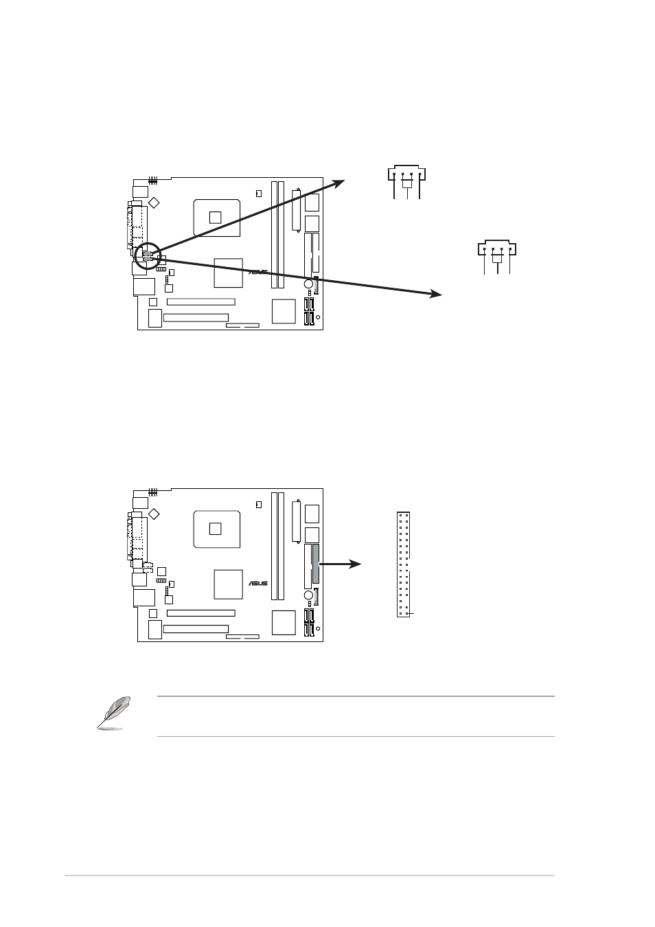
I n t e r n a l a u d i o c o n n e c t o r s ( 4 - p i n A U X , C D )
I n t e r n a l a u d i o c o n n e c t o r s ( 4 - p i n A U X , C D )
I n t e r n a l a u d i o c o n n e c t o r s ( 4 - p i n A U X , C D )
I n t e r n a l a u d i o c o n n e c t o r s ( 4 - p i n A U X , C D )
I n t e r n a l a u d i o c o n n e c t o r s ( 4 - p i n A U X , C D )
These connectors allow you to receive stereo audio input from sound
sources such as a CD-ROM, TV tuner, or MPEG card.
9 .
9 .
9 .
9 .
9 .
F l o p p y d i s k d r i v e c o n n e c t o r ( 3 4 - 1 p i n F L O P P Y )
F l o p p y d i s k d r i v e c o n n e c t o r ( 3 4 - 1 p i n F L O P P Y )
F l o p p y d i s k d r i v e c o n n e c t o r ( 3 4 - 1 p i n F L O P P Y )
F l o p p y d i s k d r i v e c o n n e c t o r ( 3 4 - 1 p i n F L O P P Y )
F l o p p y d i s k d r i v e c o n n e c t o r ( 3 4 - 1 p i n F L O P P Y )
This connector is for the provided floppy disk drive (FDD) signal cable.
Insert one end of the cable to this connector, then connect the other
end to the signal connector at the back of the floppy disk drive.
Pin 5 on the connector is removed to prevent incorrect cable connection
when using an FDD cable with a covered Pin 5.
¤
Internal audio connectors
AUX
(white)
CD
(black)
Right A
udio Channel
Left A
udio Channel
Ground
Right A
udio Channel
Left A
udio Channel
Ground
¤
FLOPPY
NOTE: Orient the red markings on
the floppy ribbon cable to PIN 1.
PIN 1
Floppy disk drive connector