Asus T2-PE1 User Manual
Page 39
2 - 2 1
2 - 2 1
2 - 2 1
2 - 2 1
2 - 2 1
A S U S T 2 - P E 1
A S U S T 2 - P E 1
A S U S T 2 - P E 1
A S U S T 2 - P E 1
A S U S T 2 - P E 1
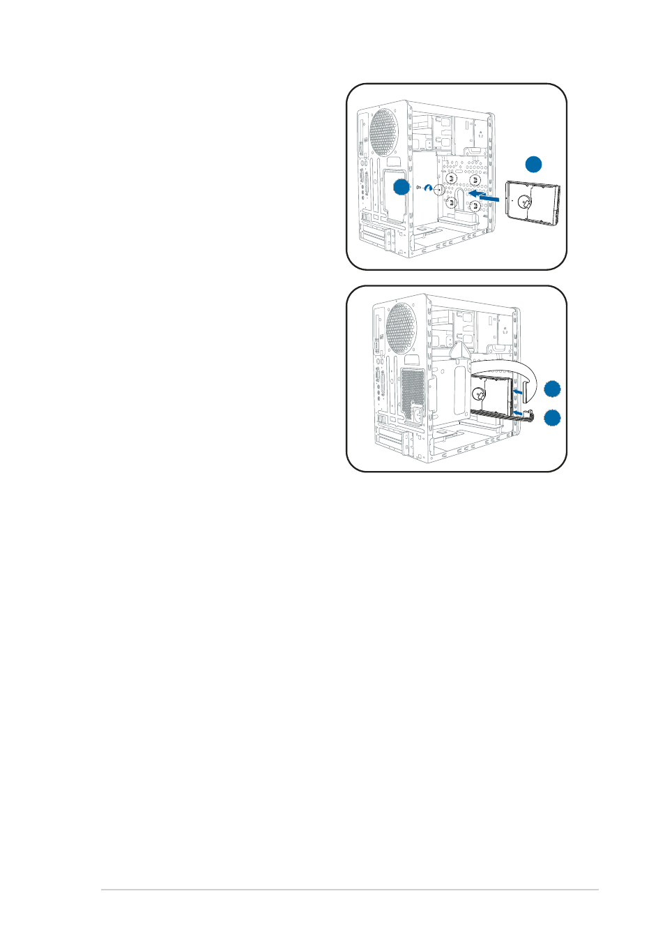
6.
Reinstall the tray and the HDD
to the chassis by locking the
tray slots to the chassis hooks.
7.
Secure the tray with the screw
you removed earlier.
8.
Connect one end of the 40-pin
IDE cable to the IDE connector
on the drive.
9.
Connect a 4-pin power plug
from the power supply unit to
the HDD power connector. See
page 2-24 for details on the
power supply unit plugs.
10. Connect the other end of the
IDE ribbon cable to the primary
IDE connector (blue connector
labeled PRI_IDE) on the
motherboard. See page 4-6 for
the location of the primary IDE
connector.
6
6
6
6
6
7
7
7
7
7
8
8
8
8
8
9
9
9
9
9
See also other documents in the category Asus Computers:
- CG8565 (410 pages)
- CG8565 (246 pages)
- CS5111 (26 pages)
- CS5120 (1 page)
- ET1611PUK (38 pages)
- S2-P8H61E (80 pages)
- P2-PH1 (80 pages)
- P1-P5945G (80 pages)
- P2-P5945GCX (90 pages)
- CG8270 (218 pages)
- CG8270 (536 pages)
- CG8270 (72 pages)
- CG8270 (76 pages)
- CG8270 (534 pages)
- CG8270 (362 pages)
- P3-P5G31 (100 pages)
- P3-PH4 (80 pages)
- P2-M2A690G (80 pages)
- P2-M2A690G (8 pages)
- P4-P5N9300 (1 page)
- P4-P5N9300 (82 pages)
- P1-P5945GC (92 pages)
- P2-P5945GC (92 pages)
- P3-P5G33 (98 pages)
- T3-P5945GC (80 pages)
- T3-P5945GCX (80 pages)
- P2-M2A690G (94 pages)
- T3-PH1 (80 pages)
- T3-PH1 (82 pages)
- T5-P5G41E (82 pages)
- T5-P5G41E (76 pages)
- S1-AT5NM10E (68 pages)
- P6-P7H55E (67 pages)
- ES5000 (174 pages)
- T4-P5G43 (104 pages)
- T-P5G31 (92 pages)
- BT6130 (60 pages)
- BT6130 (54 pages)
- BT6130 (2 pages)
- CG8265 (350 pages)
- CG8265 (210 pages)
- CM1740 (330 pages)
- CM1740 (70 pages)
- CM1740 (198 pages)
- P6-M4A3000E (59 pages)