Hardware setup, Asus cuv4x-v user’s manual 41 – Asus CUV4X-V User Manual
Page 41
ASUS CUV4X-V User’s Manual
41
3. HARDWARE SETUP
Expansion Cards
3. H/W SETUP
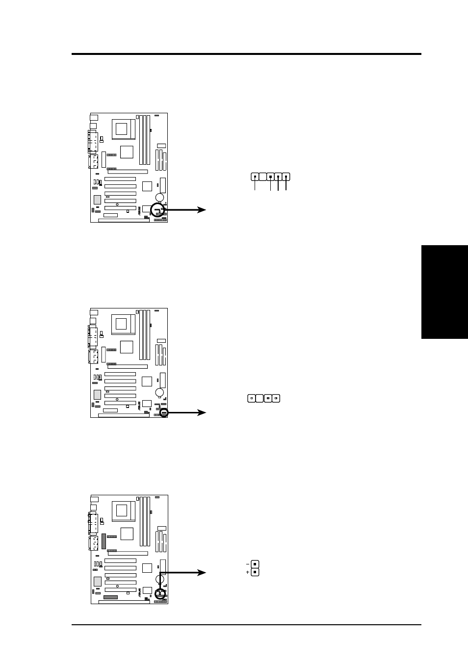
24) SMBus Connector (5-1 pin SMB)
This connector allows you to connect SMBus (System Management Bus) de-
vices. SMBus devices communicate by means of the SMBus with an SMBus
host and/or other SMBus devices.
SMBCLK
Ground
SMBDA
T
A
+5V
1
CUV4X-V SMBus Connector
SMB
®
CUV4X-V
26) IDE Activity LED (2-pin IDELED)
This connector supplies power to the cabinet’s IDE activity LED. Read and
write activity by devices connected to the Primary or Secondary IDE connectors
will cause the LED to light up.
CUV4X-V IDE Activity LED
TIP: If the case-mounted LED does not
light, try reversing the 2-pin plug.
IDELED
®
CUV4X-V
SMBus is a specific implementation of an I
2
C bus, which is a multi-
device bus; that is, multiple chips can be connected to the same bus
and each one can act as a master by initiating data transfer.
25) Chassis Intrusion Lead (4-1 pin CHASSIS)
This lead requires an external detection mechanism, such as a chassis intrusion
monitor/sensor or microswitch. The sensor is triggered when a high level signal is
sent to this lead, which occurs when a panel switch or light detector is triggered.
CUV4X-V Chassis Open Alarm Lead
CHASSIS
®
CUV4X-V
+5VSB_MB
Chassis Signal
GND
NOTE: If the chassis intrusion lead is not used, a
jumper cap must be placed over the pins to close
the circuit.