Hardware setup, Asus cuv4x-v user’s manual 37 – Asus CUV4X-V User Manual
Page 37
ASUS CUV4X-V User’s Manual
37
3. HARDWARE SETUP
Expansion Cards
3. H/W SETUP
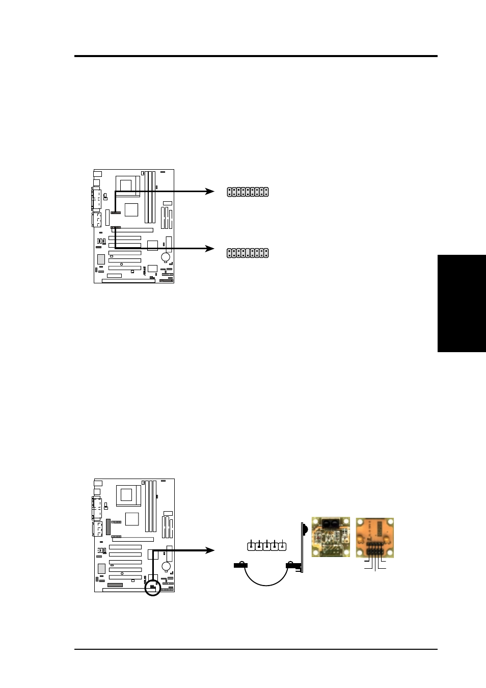
15) LCD/TV Headers (18-1 pin LCDTV / 18-pin LCDTV0)
These headers require an optional LCD module for LCD output or TV-out mod-
ule for TV output. Connect the LCD/TV-out module to the headers and mount
the bracket to the chassis on a free expansion slot.
NOTE: If both CRT and digital LCD monitors are used, the CRT will take pre-
cedence. These headers are for a digital LCD panel; an analog LCD panel comes
with a 15-pin VGA cable connector to be used on the monitor connector.
CUV4X-V LCD/TV Headers
®
CUV4X-V
LCDTV
18
17
2
1
LCDTV0
18
17
2
1
16) Standard and Consumer Infrared Module Connector (5-pin IR)
This connector supports an optional wireless transmitting and receiving infrared
module. This module mounts to a small opening on system cases that support
this feature. You must also configure the setting through UART2 Use Infrared
(see 4.4.2 I/O Device Configuration) to select whether UART2 is directed for
use with COM2 or IrDA. Use the five pins as shown in Back View and connect
a ribbon cable from the module to the motherboard’s SIR connector according
to the pin definitions. An optional consumer infrared (CIR) set connects to the
CIR and SIR connectors simultaneously for both wireless transmitting and re-
mote control functions through one external infrared module. Wake On PS2
KB/Mouse in 4.5.1 Power Up Control must be Enabled to use Consumer Infra-
red (CIR) power up.
CUV4X-V Infrared Module Connector
Front View
Back View
+5V
IRTX
IRRX
(NC)
GND
+5V
IRRX
IR
TX
(NC)
GND
IR
1
®
CUV4X-V