10 connectors – Asus P5GD2-X User Manual
Page 38
1 - 2 6
1 - 2 6
1 - 2 6
1 - 2 6
1 - 2 6
C h a p t e r 1 : P r o d u c t i n t r o d u c t i o n
C h a p t e r 1 : P r o d u c t i n t r o d u c t i o n
C h a p t e r 1 : P r o d u c t i n t r o d u c t i o n
C h a p t e r 1 : P r o d u c t i n t r o d u c t i o n
C h a p t e r 1 : P r o d u c t i n t r o d u c t i o n
3 .
3 .
3 .
3 .
3 .
R e a r S p e a k e r O u t p o r t ( g r a y ) .
R e a r S p e a k e r O u t p o r t ( g r a y ) .
R e a r S p e a k e r O u t p o r t ( g r a y ) .
R e a r S p e a k e r O u t p o r t ( g r a y ) .
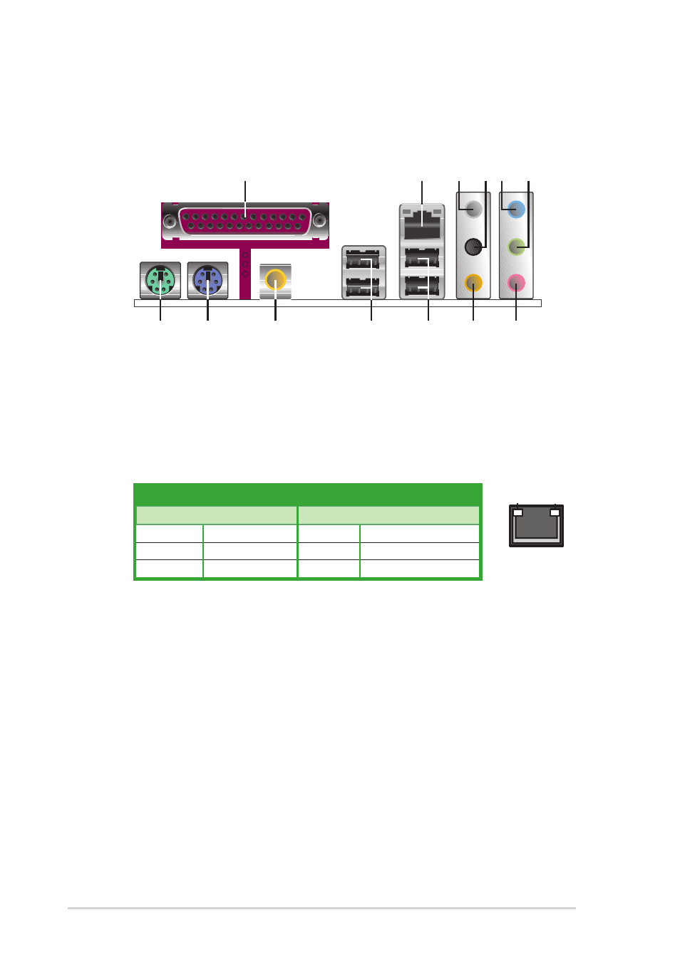
R e a r S p e a k e r O u t p o r t ( g r a y ) . This port connects the rear
speakers on a 4-channel, 6-channel, or 8-channel audio configuration.
4 .
4 .
4 .
4 .
4 .
S i d e S p e a k e r O u t p o r t ( b l a c k ) .
S i d e S p e a k e r O u t p o r t ( b l a c k ) .
S i d e S p e a k e r O u t p o r t ( b l a c k ) .
S i d e S p e a k e r O u t p o r t ( b l a c k ) .
S i d e S p e a k e r O u t p o r t ( b l a c k ) . This port connects the side
speakers in an 8-channel audio configuration.
5 .
5 .
5 .
5 .
5 .
L i n e I n p o r t ( l i g h t b l u e ) .
L i n e I n p o r t ( l i g h t b l u e ) .
L i n e I n p o r t ( l i g h t b l u e ) .
L i n e I n p o r t ( l i g h t b l u e ) .
L i n e I n p o r t ( l i g h t b l u e ) . This port connects a tape, CD, DVD
player, or other audio sources.
6 .
6 .
6 .
6 .
6 .
L i n e O u t p o r t ( l i m e ) .
L i n e O u t p o r t ( l i m e ) .
L i n e O u t p o r t ( l i m e ) .
L i n e O u t p o r t ( l i m e ) .
L i n e O u t p o r t ( l i m e ) . This port connects a headphone or a
speaker. In 4-channel, 6-channel, and 8-channel configuration, the
function of this port becomes Front Speaker Out.
7 .
7 .
7 .
7 .
7 .
M i c r o p h o n e p o r t ( p i n k ) .
M i c r o p h o n e p o r t ( p i n k ) .
M i c r o p h o n e p o r t ( p i n k ) .
M i c r o p h o n e p o r t ( p i n k ) .
M i c r o p h o n e p o r t ( p i n k ) . This port connects a microphone.
8 .
8 .
8 .
8 .
8 .
C e n t e r / S u b w o o f e r p o r t ( o r a n g e ) .
C e n t e r / S u b w o o f e r p o r t ( o r a n g e ) .
C e n t e r / S u b w o o f e r p o r t ( o r a n g e ) .
C e n t e r / S u b w o o f e r p o r t ( o r a n g e ) .
C e n t e r / S u b w o o f e r p o r t ( o r a n g e ) . This port connects the
center/subwoofer speakers.
SPEED
LED
ACT/LINK
LED
LAN port
LAN port LED indications
LAN port LED indications
LAN port LED indications
LAN port LED indications
LAN port LED indications
A C T / L I N K L E D
A C T / L I N K L E D
A C T / L I N K L E D
A C T / L I N K L E D
A C T / L I N K L E D
S P E E D L E D
S P E E D L E D
S P E E D L E D
S P E E D L E D
S P E E D L E D
S t a t u s
S t a t u s
S t a t u s
S t a t u s
S t a t u s
D e s c r i p t i o n
D e s c r i p t i o n
D e s c r i p t i o n
D e s c r i p t i o n
D e s c r i p t i o n
S t a t u s
S t a t u s
S t a t u s
S t a t u s
S t a t u s
D e s c r i p t i o n
D e s c r i p t i o n
D e s c r i p t i o n
D e s c r i p t i o n
D e s c r i p t i o n
OFF
No link
OFF
10 Mbps connection
GREEN
Linked
ORANGE
100 Mbps connection
BLINKING
Data activity
GREEN
1 Gbps connection
1.10
Connectors
1.10.1
1.10.1
1.10.1
1.10.1
1.10.1 Rear panel connectors
Rear panel connectors
Rear panel connectors
Rear panel connectors
Rear panel connectors
1.....
P a r a l l e l p o r t .
P a r a l l e l p o r t .
P a r a l l e l p o r t .
P a r a l l e l p o r t .
P a r a l l e l p o r t . This 25-pin port connects a parallel printer, a scanner,
or other devices.
2 .
2 .
2 .
2 .
2 .
L A N ( R J - 4 5 ) p o r t .
L A N ( R J - 4 5 ) p o r t .
L A N ( R J - 4 5 ) p o r t .
L A N ( R J - 4 5 ) p o r t .
L A N ( R J - 4 5 ) p o r t . This port allows Gigabit connection to a Local
Area Network (LAN) through a network hub. Refer to the table below
for the LAN port LED indications.
9
1
2
11
3
12
13
8
4 5
7
6
10