Asus F1A55-V PLUS User Manual
Page 39
4.
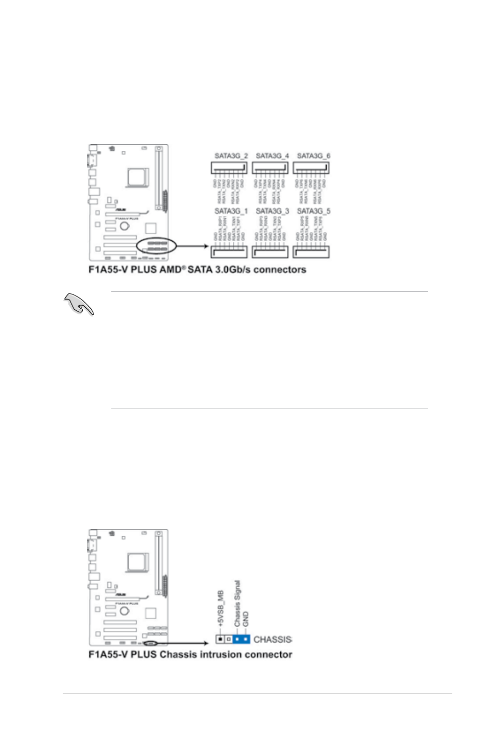
Serial ATA 3.0 Gb/s connectors (7-pin SATA3G 1~6)
These connectors are for the Serial ATA 3.0 Gb/s signal cables for Serial ATA hard
disk drives and optical disc drives. If you installed Serial ATA hard disk drives, you
can create a RAID 0, RAID 1, RAID 10, or JBOD configuration through the onboard
controller.
• These connectors are set to IDE mode by default. In IDE mode, you can connect Serial
ATA boot/data hard disk drives to these connectors. If you intend to create a Serial ATA
RAID set using these connectors, set the type of the SATA connectors in the BIOS to
[RAID]. See section 2.5.2 SATA Configuration for details.
• You must install Windows
®
XP Service Pack 3 or later version before using Serial
ATA hard disk drives. The Serial ATA RAID feature is available only if you are using
Windows
®
XP SP3 or later version.
• When using hot-plug and NCQ, set the type of the SATA connectors in the BIOS to
[AHCI]. See section 2.5.2 SATA Configuration for details.
5.
Chassis intrusion connector (4-1 pin CHASSIS)
This connector is for a chassis-mounted intrusion detection sensor or switch. Connect
one end of the chassis intrusion sensor or switch cable to this connector. The chassis
intrusion sensor or switch sends a high-level signal to this connector when a chassis
component is removed or replaced. The signal is then generated as a chassis intrusion
event.
Remove the jumper cap only when you intend to use the chassis intrusion detection
feature.
ASUS F1A55-V PLUS
1-27