Hardware setup – Asus A7V133-VM User Manual
Page 35
ASUS A7V133-VM User’s Manual
35
3. HARDWARE SETUP
Connectors
3. H/W SETUP
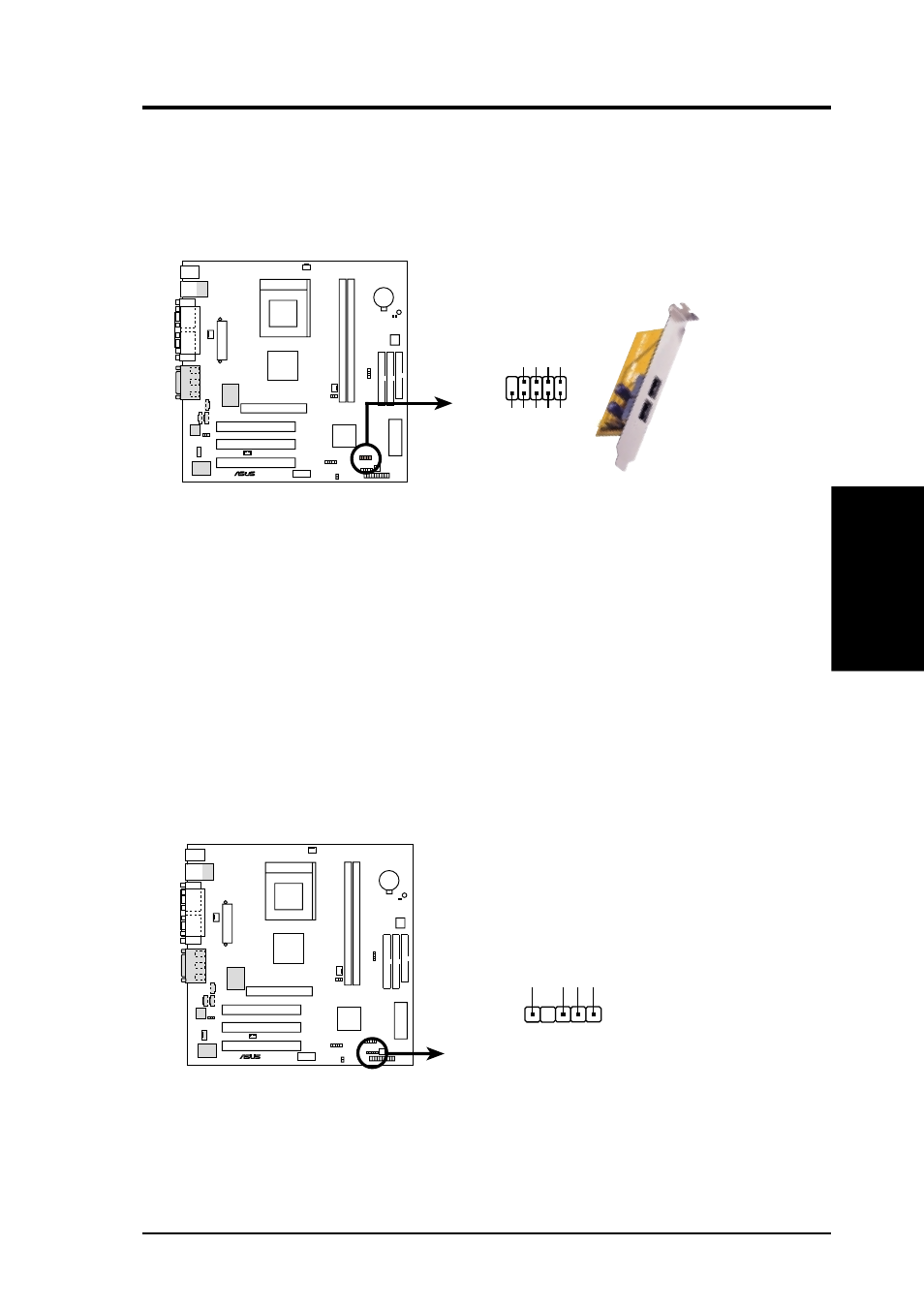
16) USB Header (10-1 pin USB2)
If the USB port connectors on the back panel are inadequate, this USB header is
available for two additional USB port connectors. Connect the USB headers to
the 2-port USB connector set and mount the bracket to an open slot on your
chassis.
17) SMBus Connector (5-1 pin SMB)
This connector allows you to connect SMBus (System Management Bus) de-
vices. SMBus devices communicate by means of the SMBus with an SMBus
host and/or other SMBus devices. SMBus is a specific implementation of an I
2
C
bus, which is a multi-device bus; that is, multiple chips can be connected to the
same bus and each one can act as a master by initiating data transfer.
A7V133-VM
®
A7V133-VM USB Port
USB Power
USBP2
–
USBP2+
GND
NC
USB Power
USBP3
–
USBP3+
GND
1
5
6
10
USB2
SMBCLK
Ground
SMBDA
T
A
+5V
1
A7V133-VM
®
A7V133-VM SMBus Connector
SMB
- P5B Premium Vista Edition (188 pages)
- P5B (140 pages)
- P5B (56 pages)
- P5KPL-VM/1394/SI (94 pages)
- M2N68-CM (28 pages)
- P5GD1-VM (92 pages)
- P5AD2-E Premium (2 pages)
- P5GD1-VM (88 pages)
- P5AD2 Premium (8 pages)
- DELUXE A7N8X-E (114 pages)
- P5KPL-AM SE (40 pages)
- P5KPL-AM SE (38 pages)
- P5KPL-AM SE (62 pages)
- P4S8X-X (64 pages)
- P5K-VM (98 pages)
- K8V-X SE (82 pages)
- M2N68-AM SE2 (40 pages)
- P4P800 SE (125 pages)
- P4P800 SE (16 pages)
- DELUXE SERIES M3A32-MVP (176 pages)
- P5AD2 Deluxe (148 pages)
- M4A79 Deluxe (122 pages)
- A7V266-E (108 pages)
- Application Manual (1 page)
- Application Manual (5 pages)
- Application Manual (11 pages)
- Application Manual (10 pages)
- Application Manual (4 pages)
- Application Manual (8 pages)
- Application Manual (2 pages)
- Application Manual (6 pages)
- Application Manual (9 pages)
- Application Manual (3 pages)
- M4A88T-I DELUXE (70 pages)
- M4A88T-I DELUXE (44 pages)
- P9X79 DELUXE (2 pages)
- RAMPAGE IV GENE (1 page)
- P9X79 (156 pages)
- P8H61-M PLUS V3 (64 pages)
- A85XM-A (78 pages)
- M4A78L-M LE (64 pages)
- M2N68-AM (96 pages)
- M2N68-AM (62 pages)
- M2N68-AM (38 pages)
- Blitz Formula (3 pages)