Asus TS500-E5/RX8 User Manual
Page 50
Chapter 2: Hardware setup
2-30
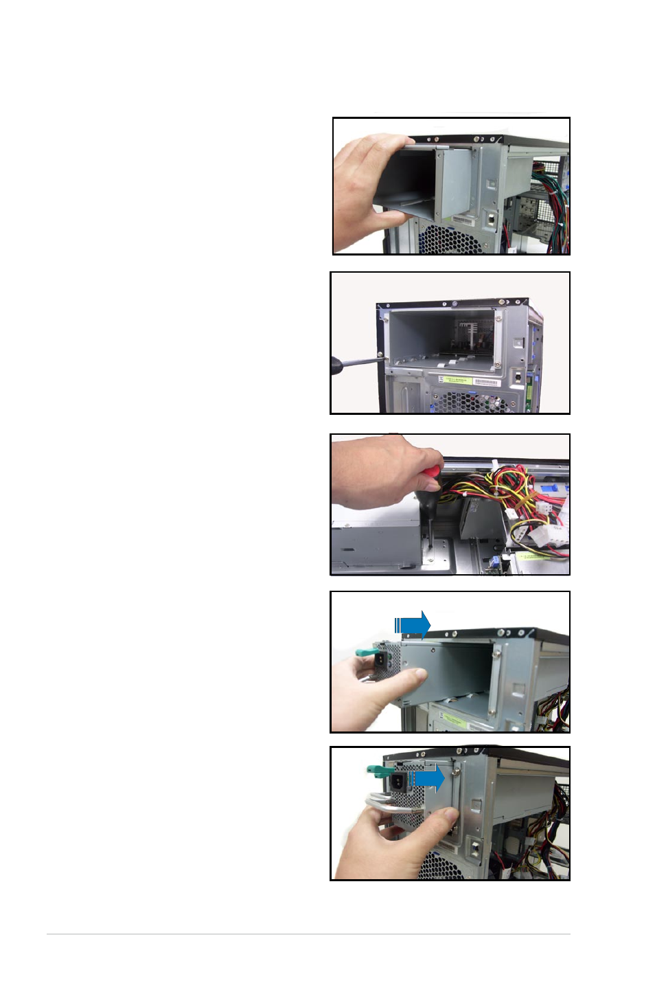
3. Insert the redundant power supply
into the power supply bay.
4. Make the redundant power supply
cage sit on the shelf ledge when
fastening it to the chassis with
screws.
5. Fasten the two screws on the
chassis wall.
6. Slide the power supply module into
the bay, and press until the release/
lock lever clicks to lock the module
securely.
7. Install the other redundant power
supply module as the first one.
This manual is related to the following products:
See also other documents in the category Asus Computer hardware:
- AP2500 (40 pages)
- AP1700-S5 (58 pages)
- RS700-E6/ERS4 (138 pages)
- AP1600R-E2(AA2) (150 pages)
- P7F-E (162 pages)
- RS161-E4/PA2 (126 pages)
- RS163-E4/RX4 (11 pages)
- M2N-LR (113 pages)
- P5BV/SAS (184 pages)
- K8N-DRE (142 pages)
- RS161-E5/PA2 (124 pages)
- LSI SAS3442X-R (68 pages)
- ESC4000/FDR G2 (200 pages)
- PIKE 2208 (16 pages)
- ESC4000 (162 pages)
- ESC4000 (22 pages)
- PSCH-SR/IDE (102 pages)
- P9D-M (156 pages)
- RS740-E7-RS24-EG (212 pages)
- P5M2-E/4L (12 pages)
- ESC2000 G2 (226 pages)
- TS700-E6/RS8 (166 pages)
- RS160-E3/PS4 (140 pages)
- PU-DLS (134 pages)
- TR-DLSR (100 pages)
- P5BV-C/2L (161 pages)
- TS100-E5/PI4 (166 pages)
- ESC1000 Personal SuperComputer (184 pages)
- NRL-LS (120 pages)
- PCI-DA2200 (369 pages)
- P8C WS (140 pages)
- RS120-E4/PA4 (174 pages)
- P5MT-M (150 pages)
- TS Mini (2 pages)
- TS Mini (112 pages)
- TS Mini (114 pages)
- P5MT-MX/C (156 pages)
- AP140R-E1 (52 pages)
- AP140R-E1 (132 pages)
- ASMB6-iKVM (114 pages)
- DSBF-D16/SAS (200 pages)
- DSBF-D16 (202 pages)
- RS160-E5 (164 pages)
- Z8PE-D12X (170 pages)
- Z8PE-D12X (168 pages)