1 overview overview overview overview overview – Asus P5RD1-V User Manual
Page 33
A S U S P 5 R D 1 - V
A S U S P 5 R D 1 - V
A S U S P 5 R D 1 - V
A S U S P 5 R D 1 - V
A S U S P 5 R D 1 - V
2 - 1 3
2 - 1 3
2 - 1 3
2 - 1 3
2 - 1 3
2.4
System memory
2.4.1
2.4.1
2.4.1
2.4.1
2.4.1
Overview
Overview
Overview
Overview
Overview
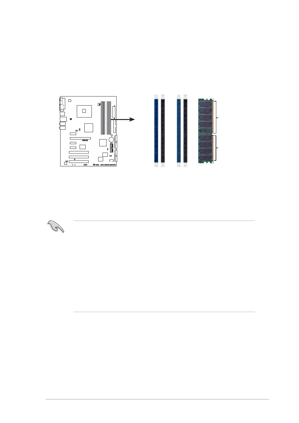
The motherboard comes with four 184-pin Double Data Rate (DDR) Dual
Inline Memory Modules (DIMM) sockets.
The following figure illustrates the location of the sockets:
2.4.2
2.4.2
2.4.2
2.4.2
2.4.2
Memory configurations
Memory configurations
Memory configurations
Memory configurations
Memory configurations
You may install 256 MB, 512 MB and 1 GB unbuffered non-ECC DDR DIMMs
into the DIMM sockets using the memory configurations in this section.
•
Installing DDR DIMMs other than the recommended configurations
may cause memory sizing error or system boot failure. Use any of
the recommended configurations in Table 1.
•
In dual-channel configurations, install only i d e n t i c a l
i d e n t i c a l
i d e n t i c a l
i d e n t i c a l
i d e n t i c a l (the same
type and size) DDR DIMM pairs for each channel.
•
Always install DIMMs with the same CAS latency. For optimum
compatibility, it is recommended that you obtain memory modules
from the same vendor.
•
Due to chipset resource allocation, the system may detect less than
4 GB system memory when you installed four 1 GB DDR memory
modules.
P5RD1-V
®
P5RD1-V 184-pin DDR DIMM sockets
DIMM_A1
DIMM_A2
DIMM_B1
DIMM_B2
80 Pins
104 Pins