Iii. hardware setup, 29 asus mel-c user’s manual – Asus MEL-C User Manual
Page 29
29
ASUS MEL-C User’s Manual
III. HARDWARE SETUP
Connectors
III. H/W SETUP
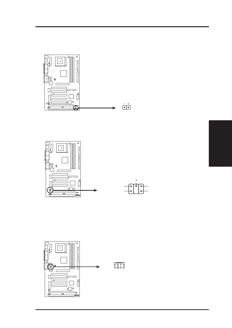
15. IDE Device Activity LED (2-pin IDELED)
This connector supplies power to the cabinet’s hard disk or IDE activity LED.
Read and write activity by devices connected to the Primary or Secondary IDE
connectors will cause the LED to light up.
MEL-C IDE Activity LED
TIP: If the case-mounted LED does not
light, try reversing the 2-pin plug.
IDELED
16. SB-Link™ Connector (6-1 pin SBLINK)
If you have a Sound Blaster compatible PCI audio card, you must link it to this
connector. Otherwise, you will have compatibility issues under DOS environment.
MEL-C SB-Link™ Connector
NOTE: Pin 3 is removed to ensure the
correct orientation of the cable on it.
PC/PCI Grant
Sideband Signal
5
6
PC/PCI Request
Sideband Signal
1
DGND
2
DGND
Serial IRQ
4
17. Voice Modem In Connector (4-pin MODEM)
This connector allows the onboard audio to interface with a voice modem card.
It also allows the sharing of microphone and speaker between the onboard audio
and the voice modem card. NOTE: Your voice modem card requires a similar
connector to use this feature.
MEL-C Modem Card Voice In Connector
MODEM
Modem-In
Ground
Modem-Out
Ground