Iii. hardware setup, 25 asus mel-c user’s manual – Asus MEL-C User Manual
Page 25
25
ASUS MEL-C User’s Manual
III. HARDWARE SETUP
Connectors
III. H/W SETUP
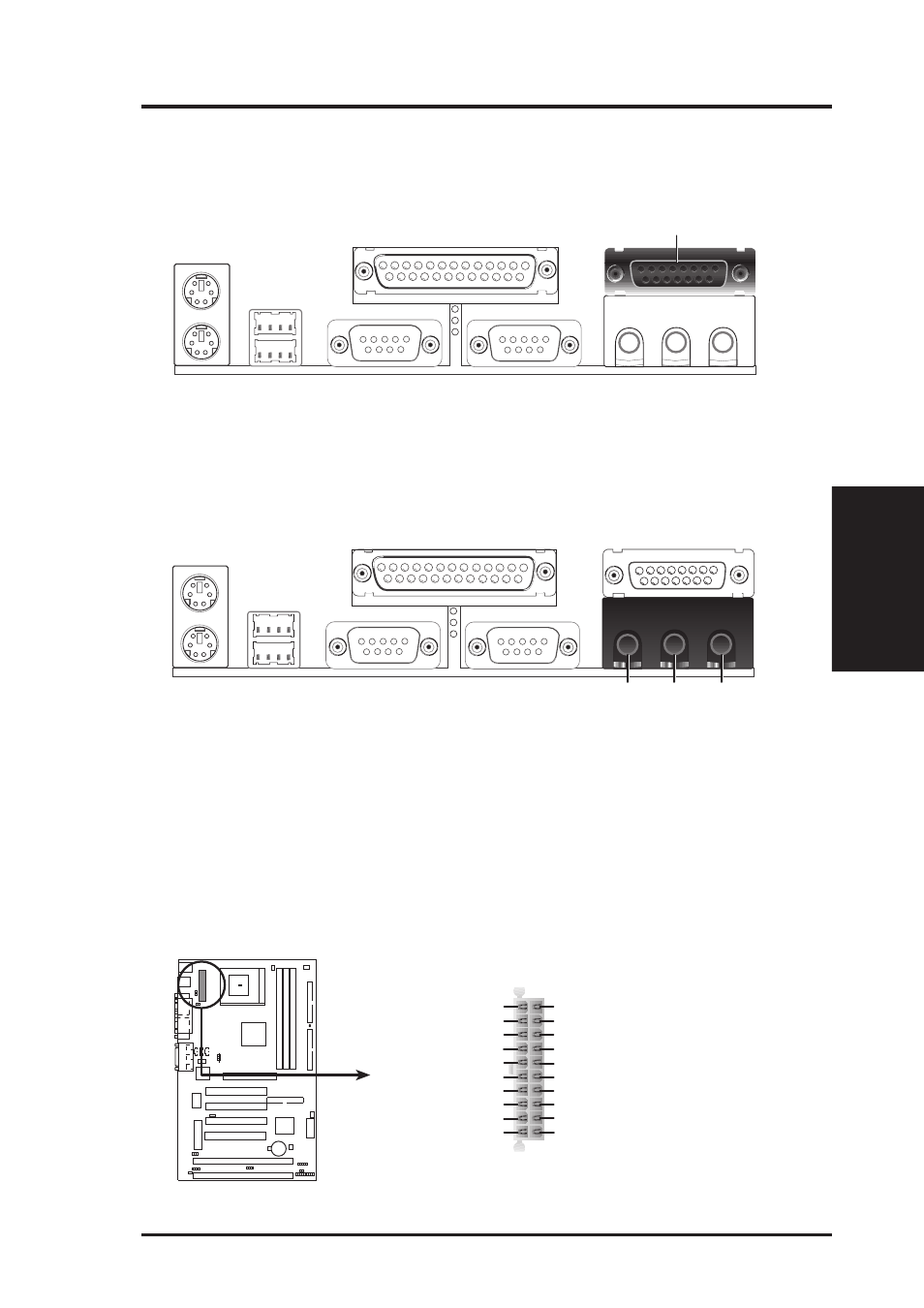
6. Joystick/Midi Connector (15-pin GAME_AUDIO)
You may connect game joysticks or game pads to this connector for playing
games. Connect MIDI devices for playing or editing audio.
Joystick/Midi (15-pin Female)
7. Audio Port Connectors (Three 1/8” GAME_AUDIO)
Line Out can be connected to headphones or preferably powered speakers.
Line In allows tape players or other audio sources to be recorded by your com-
puter or played through the Line Out. Mic allows microphones to be connected
for inputing voice.
Mic
Line In
Line Out
1/8" Stereo Audio Connectors
8. ATX Power Supply Connector (20-pin block ATXPWR)
This connector connects to an ATX power supply. The plug from the power sup-
ply will only insert in one orientation because of the different hole sizes. Find the
proper orientation and push down firmly making sure that the pins are aligned.
IMPORTANT:
Make sure that your ATX power supply can supply at least 10mA
on the +5-volt standby lead (+5VSB). You may experience difficulty in power-
ing on your system if your power supply cannot support the load. For Wake-On-
LAN support, your ATX power supply must supply at least 720mA +5VSB.
MEL-C ATX Power Connector
+3.3Volts
-12.0Volts
Ground
Power Supply On
Ground
Ground
Ground
-5.0 Volts
+5.0 Volts
+5.0 Volts
Power Good
+12.0Volts
+3.3 Volts
+3.3 Volts
Ground
+5.0 Volts
Ground
+5.0 Volts
Ground
+5V Standby