3 accelerated processing unit (apu), Accelerated processing unit (apu) -4, 4 layout contents – Asus A55BM-PLUS User Manual
Page 12
1-4
Chapter 1: Product introduction
1.2.4
Layout contents
A55BM-PLUS
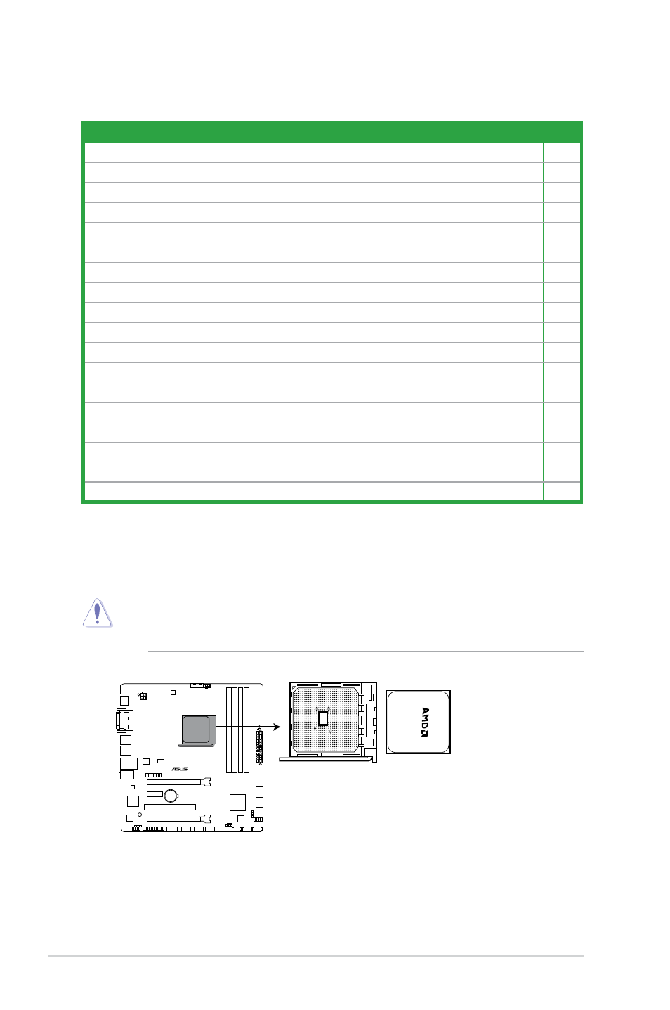
A55BM-PLUS CPU socket FM2+
1.3
Accelerated Processing Unit (APU)
This motherboard comes with a FM2+ socket designed for AMD
®
A-series and Athlon™
series processors.
Ensure that you use an APU designed for the FM2+ socket. The APU fits in only one
correct orientation. DO NOT force the APU into the socket to prevent bending the pins and
damaging the APU!
Connectors/Jumpers/Slots/LED
Page
1. ATX power connectors (24-pin EATXPWR, 4-pin ATX12V)
1-18
2. CPU and chassis fan connectors (4-pin CPU_FAN, and 4-pin CHA_FAN)
1-17
3. AMD FM2+ socket
1-4
4. GPU Boost switch
1-14
5. DDR3 DIMM slots
1-8
6. MemOK! button
1-13
7. Speaker connector (4-pin SPEAKER)
1-20
8. SATA 3.0 Gb/s connectors (7-pin SATA3G_1~6)
1-19
9. System panel connector (10-1 pin F_PANEL)
1-20
10. Clear RTC RAM (3-pin CLRTC)
1-12
11. Chassis intrusion connector (4-1 pin CHASSIS)
1-17
12. USB 2.0 connector (10-1 pin USB910, USB78, USB56)
1-22
13. Serial port connector (10-1 pin COM)
1-23
14. LPT connector (26-1 pin LPT)
1-23
15. Digital audio connector (4-1 pin SPDIF_OUT)
1-21
16. Front panel audio connector (10-1 pin AAFP)
1-21
17. Standby power LED (SB_PWR)
1-1
18. TPM connector (20-1 pin TPM)
1-22