12 replacing the cover – Asus Terminator A7VT400 User Manual
Page 37
2 - 2 1
2 - 2 1
2 - 2 1
2 - 2 1
2 - 2 1
A S U S T e r m i n a t o r 1 A 7 V T 4 0 0
A S U S T e r m i n a t o r 1 A 7 V T 4 0 0
A S U S T e r m i n a t o r 1 A 7 V T 4 0 0
A S U S T e r m i n a t o r 1 A 7 V T 4 0 0
A S U S T e r m i n a t o r 1 A 7 V T 4 0 0
2.12
Replacing the cover
After you have installed all the internal components and you have
connected all the necessary cables, you are now ready to put the system
back together.
To re-assemble the system:
1.
With the chassis lying on its
side, hook the swivel edge of
the drive frame to the main
chassis.
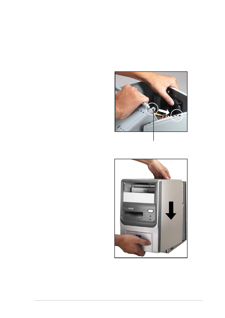
2.
Sway the drive frame inward
until it fits completely. The
protruding tabs on both ends
of the drive frame should snap
perfectly to the chassis edge.
P r o t r u d i n g t a b
P r o t r u d i n g t a b
P r o t r u d i n g t a b
P r o t r u d i n g t a b
P r o t r u d i n g t a b
3.
Turn the chassis upright.
4.
Place the cover over the
chassis leaving about two
inches from the rear panel.
- CG8565 (410 pages)
- CG8565 (246 pages)
- CS5111 (26 pages)
- CS5120 (1 page)
- ET1611PUK (38 pages)
- S2-P8H61E (80 pages)
- P2-PH1 (80 pages)
- P1-P5945G (80 pages)
- P2-P5945GCX (90 pages)
- CG8270 (218 pages)
- CG8270 (536 pages)
- CG8270 (72 pages)
- CG8270 (76 pages)
- CG8270 (534 pages)
- CG8270 (362 pages)
- P3-P5G31 (100 pages)
- P3-PH4 (80 pages)
- P2-M2A690G (80 pages)
- P2-M2A690G (8 pages)
- P4-P5N9300 (1 page)
- P4-P5N9300 (82 pages)
- P1-P5945GC (92 pages)
- P2-P5945GC (92 pages)
- P3-P5G33 (98 pages)
- T3-P5945GC (80 pages)
- T3-P5945GCX (80 pages)
- P2-M2A690G (94 pages)
- T3-PH1 (80 pages)
- T3-PH1 (82 pages)
- T5-P5G41E (82 pages)
- T5-P5G41E (76 pages)
- S1-AT5NM10E (68 pages)
- P6-P7H55E (67 pages)
- ES5000 (174 pages)
- T4-P5G43 (104 pages)
- T-P5G31 (92 pages)
- BT6130 (60 pages)
- BT6130 (54 pages)
- BT6130 (2 pages)
- CG8265 (210 pages)
- CG8265 (350 pages)
- CM1740 (330 pages)
- CM1740 (70 pages)
- CM1740 (198 pages)
- P6-M4A3000E (59 pages)