3 removing the cover – Asus Terminator A7VT400 User Manual
Page 19
2 - 3
2 - 3
2 - 3
2 - 3
2 - 3
A S U S T e r m i n a t o r 1 A 7 V T 4 0 0
A S U S T e r m i n a t o r 1 A 7 V T 4 0 0
A S U S T e r m i n a t o r 1 A 7 V T 4 0 0
A S U S T e r m i n a t o r 1 A 7 V T 4 0 0
A S U S T e r m i n a t o r 1 A 7 V T 4 0 0
2.3
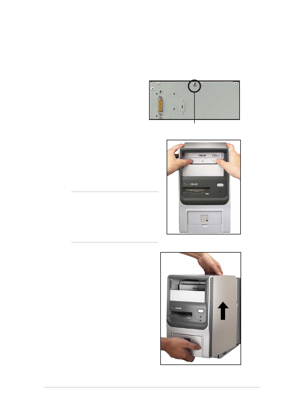
Removing the cover
The chassis cover is secured by a screw located on the rear panel.
To remove the chassis cover:
1.
Turn the screw
counterclockwise to release
the cover. Set the screw
aside.
2.
Place your hands on both
corners of the front panel, just
beside the CD-ROM frame.
Push on the CD-ROM area with
your thumbs until the cover
tilts forward.
3.
While supporting the front
panel with one hand, place
your other hand on the top
rear edge of the cover and
carefully lift the cover from
the chassis.
Screw
T I P
T I P
T I P
T I P
T I P
Another way to release the cover is
to place your hands underneath the
front panel edge, then push the
inner chassis with your thumbs
while pulling the panel with your
other fingers.
- CG8565 (410 pages)
- CG8565 (246 pages)
- CS5111 (26 pages)
- CS5120 (1 page)
- ET1611PUK (38 pages)
- S2-P8H61E (80 pages)
- P2-PH1 (80 pages)
- P1-P5945G (80 pages)
- P2-P5945GCX (90 pages)
- CG8270 (218 pages)
- CG8270 (536 pages)
- CG8270 (72 pages)
- CG8270 (76 pages)
- CG8270 (534 pages)
- CG8270 (362 pages)
- P3-PH4 (80 pages)
- P3-P5G31 (100 pages)
- P2-M2A690G (80 pages)
- P2-M2A690G (8 pages)
- P4-P5N9300 (82 pages)
- P4-P5N9300 (1 page)
- P1-P5945GC (92 pages)
- P2-P5945GC (92 pages)
- P3-P5G33 (98 pages)
- T3-P5945GC (80 pages)
- T3-P5945GCX (80 pages)
- P2-M2A690G (94 pages)
- T3-PH1 (80 pages)
- T3-PH1 (82 pages)
- T5-P5G41E (82 pages)
- T5-P5G41E (76 pages)
- S1-AT5NM10E (68 pages)
- P6-P7H55E (67 pages)
- ES5000 (174 pages)
- T4-P5G43 (104 pages)
- T-P5G31 (92 pages)
- BT6130 (60 pages)
- BT6130 (54 pages)
- BT6130 (2 pages)
- CG8265 (210 pages)
- CG8265 (350 pages)
- CM1740 (330 pages)
- CM1740 (70 pages)
- CM1740 (198 pages)
- P6-M4A3000E (59 pages)