Asus Terminator A7VT400 User Manual
Page 25
2 - 9
2 - 9
2 - 9
2 - 9
2 - 9
A S U S T e r m i n a t o r 1 A 7 V T 4 0 0
A S U S T e r m i n a t o r 1 A 7 V T 4 0 0
A S U S T e r m i n a t o r 1 A 7 V T 4 0 0
A S U S T e r m i n a t o r 1 A 7 V T 4 0 0
A S U S T e r m i n a t o r 1 A 7 V T 4 0 0
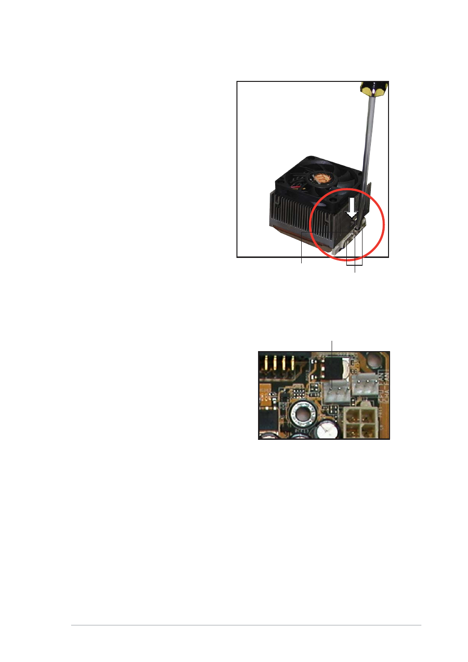
4.
Connect the CPU fan cable
from the assembly to the fan
connector labeled CPU_FAN1.
C P U f a n c o n n e c t o r
C P U f a n c o n n e c t o r
C P U f a n c o n n e c t o r
C P U f a n c o n n e c t o r
C P U f a n c o n n e c t o r
( C P U _ F A N 1 )
( C P U _ F A N 1 )
( C P U _ F A N 1 )
( C P U _ F A N 1 )
( C P U _ F A N 1 )
S o c k e t t a b s
S o c k e t t a b s
S o c k e t t a b s
S o c k e t t a b s
S o c k e t t a b s
H e a t s i n k b r a c k e t
H e a t s i n k b r a c k e t
H e a t s i n k b r a c k e t
H e a t s i n k b r a c k e t
H e a t s i n k b r a c k e t
3.
Using a flat screwdriver,
carefully hook the other end of
the heatsink bracket to the
tabs on the base of the CPU
socket. This secures the fan
and heatsink assembly.
- CG8565 (410 pages)
- CG8565 (246 pages)
- CS5120 (1 page)
- CS5111 (26 pages)
- ET1611PUK (38 pages)
- S2-P8H61E (80 pages)
- P1-P5945G (80 pages)
- P2-P5945GCX (90 pages)
- P2-PH1 (80 pages)
- CG8270 (534 pages)
- CG8270 (362 pages)
- CG8270 (218 pages)
- CG8270 (536 pages)
- CG8270 (72 pages)
- CG8270 (76 pages)
- P3-P5G31 (100 pages)
- P3-PH4 (80 pages)
- P2-M2A690G (8 pages)
- P2-M2A690G (80 pages)
- P4-P5N9300 (82 pages)
- P4-P5N9300 (1 page)
- P2-P5945GC (92 pages)
- P1-P5945GC (92 pages)
- P3-P5G33 (98 pages)
- T3-P5945GC (80 pages)
- T3-P5945GCX (80 pages)
- P2-M2A690G (94 pages)
- T3-PH1 (80 pages)
- T3-PH1 (82 pages)
- T5-P5G41E (76 pages)
- T5-P5G41E (82 pages)
- S1-AT5NM10E (68 pages)
- P6-P7H55E (67 pages)
- ES5000 (174 pages)
- T4-P5G43 (104 pages)
- T-P5G31 (92 pages)
- BT6130 (60 pages)
- BT6130 (54 pages)
- BT6130 (2 pages)
- CG8265 (350 pages)
- CG8265 (210 pages)
- CM1740 (330 pages)
- CM1740 (70 pages)
- CM1740 (198 pages)
- P6-M4A3000E (59 pages)