3 motherboard layout, 4 layout contents, Motherboard layout -6 – Asus P8H61-M LK R2.0 User Manual
Page 18: Layout contents -6, Chapter 1: product introduction
1-6
Chapter 1: Product introduction
1.3.3
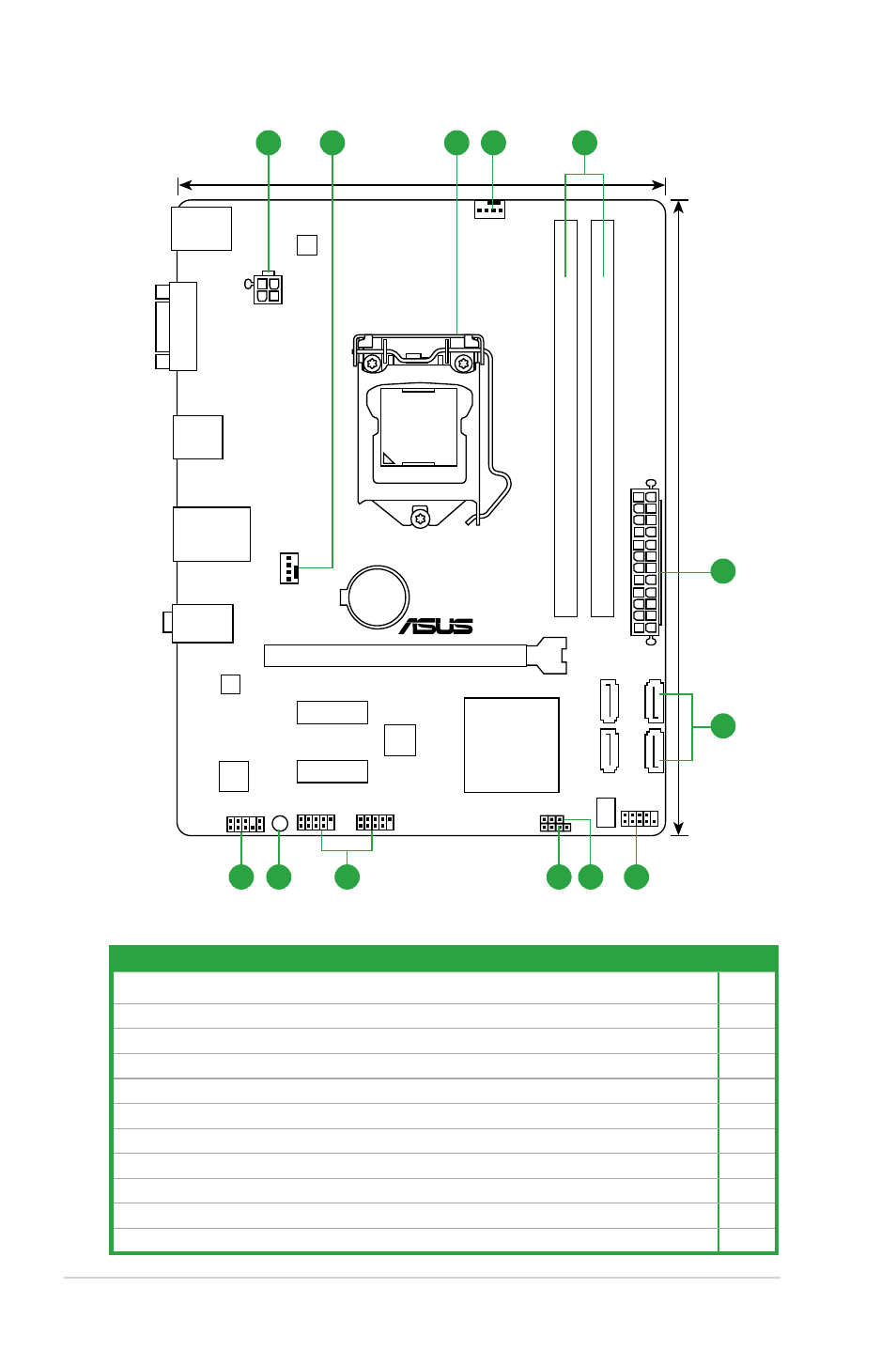
Motherboard layout
PCIEX16
PCIEX1_2
USB56
USB910
F_PANEL
SPEAKER
CLRTC
AAFP
ATX12V
EATXPWR
CPU_FAN
CHA_FAN
Lithium Cell
CMOS Power
Super
I/O
ALC
887
RTL
8111F
EPU
64Mb
BIOS
SB_PWR
22.6cm (8.9in)
DDR3 DIMM_A1 (64bit, 240-pin module)
LGA1155
DDR3 DIMM_B1 (64bit, 240-pin module)
SATA3G_2
SATA3G_4
SATA3G_1
SATA3G_3
AUDIO
KBMS
LAN_USB12
USB34
17.3cm (6.8in)
VGA
Intel
®
H61
PCIEX1_1
2
1
3
4
2
1
6
8
9
7
10
11
5
P8H61-M LK R2.0
1.3.4
Layout contents
Connectors/Jumpers/Slots/LED
Page
1. ATX power connectors (24-pin EATXPWR, 4-pin ATX12V)
1-21
2. CPU and chassis fan connectors (4-pin CPU_FAN and 4-pin CHA_FAN)
1-22
3. Intel
®
LGA1155 CPU socket
1-7
4. DDR3 DIMM slots
1-12
5. Intel
®
H61 Serial ATA 3.0Gb/s connectors (7-pin SATA3G_1/2/3/4)
1-24
6. System panel connector (10-1 pin PANEL)
1-25
7. Clear RTC RAM (3-pin CLRTC)
1-18
8. Speaker connector (4-pin SPEAKER)
1-21
9. USB 2.0 connectors (10-1 pin USB56, USB78)
1-23
10. Standby power LED (SB_PWR)
1-4
11. Front panel audio connector (10-1 pin AAFP)
1-20