21 b a – Net Optics 4 Station Bypass Switch w_Heartbeat User Manual
Page 16
12
4 Station Bypass Switch with Heartbeat
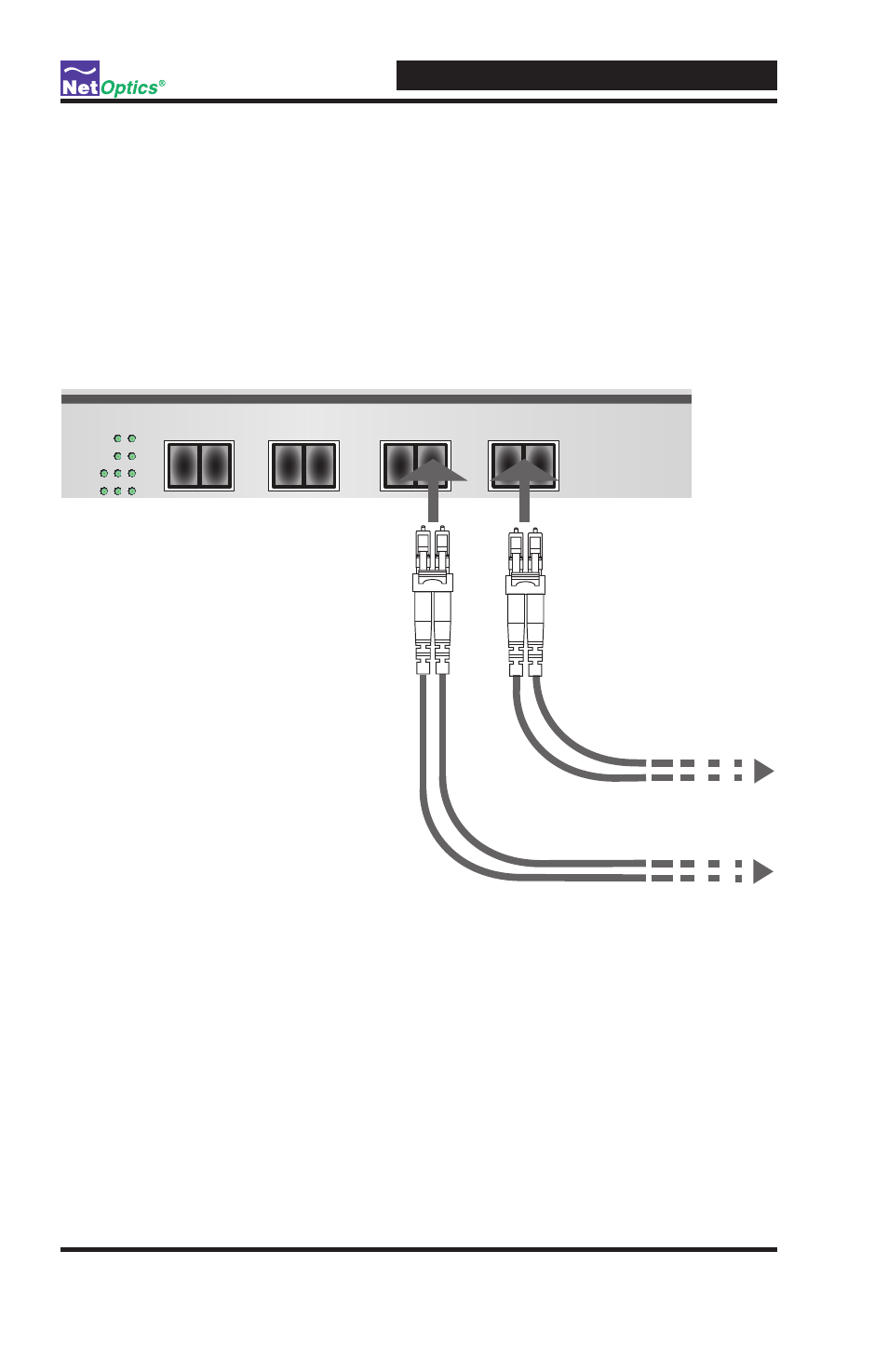
Connecting to the Monitoring Device
To connect a bypass switch segment to the in-line device:
1 . Connect Monitoring Port 1 to the appropriate in-line appliance . This acts
as your DCE interface.
2 . Connect Monitoring Port 2 to the appropriate in-line appliance .
This acts as your DTE interface.
Figure 8: Connecting one Bypass Switch segment to the Monitoring Device
3. Verify that the bypass switch Monitoring Ports are cabled in-line to the
attached device .
4. Repeat steps 1-3 for the remaining segments.
5. Connect power to the switch. If you are implementing power fault failover,
make sure you connect the switches' power supplies to the same power
sources that the IPS is using.
®
Network
Monitor
2
1
B
A
Network
Monitor
2
1
B
A
Network
Monitor
2
1
B
A
Network
Monitor
2
1
1
2
B
A
Rx
B
To monitoring device
To monitoring device
Tx
A