Ilink agg, Checking the installation, Doubling your ports – Net Optics iLink Agg Link Aggregator Tap User Manual
Page 2: Mapping ports, Connecting to the network, Connecting to monitoring devices
Checking the Installation
After you have connected iLink Agg, verify that it is
functioning correctly.
Check that the power LEDs are illuminated.
Check the link LEDs for each of the connected ports to
YHULI\WKDWWKHOLQNVDUHFRQQHFWHGDQGWUDI¿FLVSUHVHQW
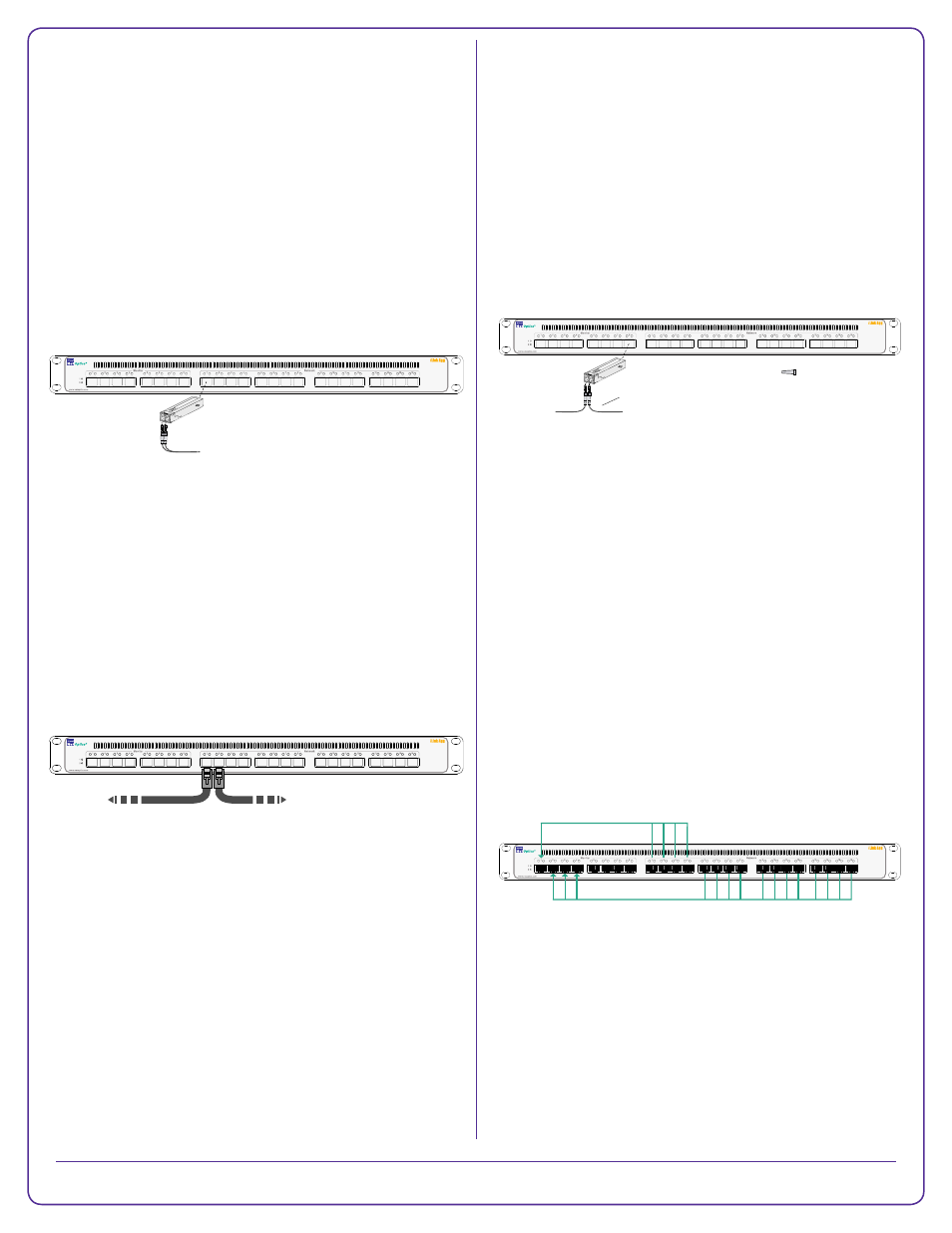
Doubling Your Ports
%\XVLQJVLPSOH[VLQJOH¿EHUFDEOHV¿EHUSRUWVFDQ
be used as Span network inputs and monitor outputs
simultaneously, making up to 24 network and 24 monitor
ports available for use. This can be done because the TX
and RX sides of the ports are completely independent.
Mapping Ports
7KHL/LQN$JJLVVKLSSHGLQDFRQ¿JXUDWLRQWKDWDJJUHJDWHV
WKHWUDI¿FIURPWKHQHWZRUNSRUWVDQGUHJHQHUDWHVLWWR
WKHPRQLWRUSRUWV$YDULHW\RIDOWHUQDWHFRQ¿JXUDWLRQV
are preloaded;; they can be viewed by typing FRQ¿JOLVW
and loaded by typing FRQ¿JORDG¿OH FRQ¿JXUDWLRQ
QDPH! followed by FRPPLW. See the User Guide for
GLDJUDPVRIWKHSUHORDGHGFRQ¿JXUDWLRQV
to aggregate 4 network ports to 1 monitor port and the
other 12 network ports to 3 monitor ports, use these
commands:
PDSGLVFDUGFOHDUWKHFXUUHQWFRQ¿JXUDWLRQ
map add in_ports=n1.1-n1.4 outports=m.1
map add in_ports=n1.5-n1.16 outports=m.2,m.3,m.4
FRPPLW
FRQ¿JVDYH¿OH P\&RQ¿JVDYHWKHFR¿JXUDWLRQIRU
future use
³P\&RQ¿J´3RUW0DSSLQJ
Note: Each network input can be used in only one
in_ports list. FRPPLW must be executed to activate the
added maps.
)RUPRUHLQIRUPDWLRQVHHWKHL/LQN$JJ8VHU*XLGH
38%/$8SGILQFOXGHGRQWKHL/LQN$JJ&'
© 2012 by Net Optics, Inc. Net Optics® is a registered trademark of Net Optics, Inc. iLink Agg
TM
is a trademark of Net Optics, Inc.
800-0128-001 rev B PUBDIRPQ 3/10
To monitoring
device
From Span port
TX RX
Caution! Install dust plugs in the unused sides
of the ports on the montioring device and switch
Simplex cables
Connecting to the Network
Note: SFP modules may be shipped separately. An
appropriate cable is shipped with each SFP module.
7RFRQQHFWL/LQN$JJWRD6SDQSRUWRUH[WHUQDO7DSRQ
\RXUQHWZRUN
1. Remove the temporary plug from an SFP slot and insert
the SFP module until it clicks into place. The SFP slot
can be a network port on a Span model iLink Agg or a
monitor port on any model.
2. Connect the cable supplied with the SFP module to the
SFP port.
3. Connect the other end of the cable to a Span port on a
network switch. Alternately, it can be connected to an
external Tap or Port Aggregator Tap.
7RFRQQHFWL/LQN$JJLQOLQHWR\RXUQHWZRUN
1. Connect any odd-numbered network port on in-line
model iLink Agg to an appropriate network cable.
2. Connect the other end of the cable to one side of the
network link you are tapping.
3. Connect the next higher even-numbered network port
to an appropriate network cable. In-line port pairs are
located side-by-side.
4. Connect the other end of the cable to the other side of
the network link you are tapping. The Tap connection
LVIXOO\SDVVLYH±LIWKHL/LQN$JJORVHVSRZHUWUDI¿F
FRQWLQXHVWRÀRZLQWKHOLQN
Connecting to Monitoring Devices
7RFRQQHFWL/LQN$JJWRDPRQLWRULQJGHYLFH
1. Remove the temporary plug from an SFP slot and
insert the SFP module until it clicks into place. The SFP
slot can be a network port on a Span model iLink Agg
or a monitor port on any model.
2. Connect the cable supplied with the SFP module to the
SFP port.
3. Connect the other end of the cable to the monitoring
device.
Note: Span network ports can also be used as
monitoring outputs, and monitor ports can also be used
as Span network inputs.
To Span port or Tap
To network switch A
To network switch B
iLink Agg
TM