Dayton Audio RS621CMK Speaker Kit Pair Curved Maple User Manual
Page 5
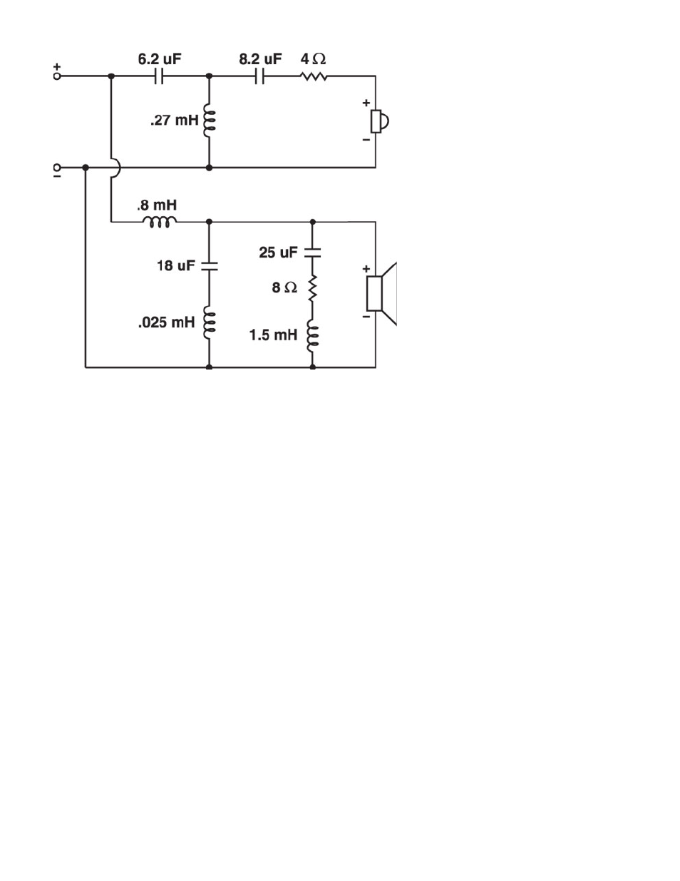
Indicator
Description
C1
Dayton DMPC-6.2 6.2uF 250V Polypropylene Capacitor
C2
Dayton DMPC-8.2 8.2uF 250V Polypropylene Capacitor
C3
Dayton DMPC-18 18uF 250V Polypropylene Capacitor
C4
Dayton DMPC-25 25uF 250V Polypropylene Capacitor
L1
Jantzen 0.27mH 18 AWG Air Core Inductor
L2
Jantzen 0.80mH 18 AWG Air Core Inductor
L3
Jantzen 0.025mH 18 AWG Air Core Inductor
L4
Jantzen 1.5mH 18 AWG Air Core Inductor
R1
Dayton DNR-4.0 4 Ohm 10W Non-Inductive Resistor
R2
Dayton DNR-8.0 8 Ohm 10W Non-Inductive Resistor
Each component will have two leads that correspond to holes on the PC board. Put the components into place with
the leads going through their appropriate holes, following the pictorial on the board. Directionality on the components
is not important; either end of each component can go into either hole. It is recommended that each component be
secured to the board with hot-melt or silicone to prevent any possible vibration of components. Cable ties are
recommended on the inductors to hold them in place more firmly, especially if you are using silicone.
Once all of the components have been secured and have their leads going through the board, we can flip it over and
make the solder connections. To solder effectively, place the soldering iron tip so that it is touching both the
component lead and the PC board. This will allow both portions to heat simultaneously, and will ensure a good flow
of solder between the two. After heating the board and leads for several seconds, add solder to the joint to form an
effective connection. A good solder joint will have a conical shape, and will not look “blobby” or “spherical.”
On the inductors, make sure that the “silver” tinned section of the lead is what you are soldering to. Attempting to
solder to the copper-colored or red insulated portion of the inductor lead will result in a failed connection. After all
connections are made, the remaining component leads on the rear of the board can be trimmed down with a pair of
side cutters or other electrical cutters.