Connector types and pin definitions, A. connector types and pin definitions – SCANTECH ID (Champtek company) MICA M-9030 User Manual
Page 31
Appendices
25
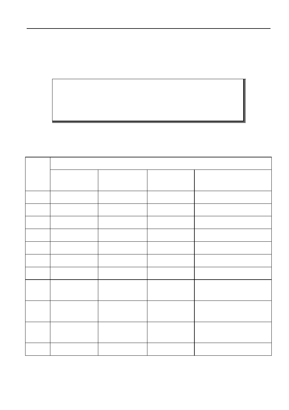
A. CONNECTOR TYPES AND PIN DEFINITIONS
This scanner supports multiple interface: RS232, KBW (Keyboard Wedge), USB, and
Powered USB. The various pin definitions for each type of interface are given below.
IMPORTANT
Various interface cables are available depending on the kind of
host system you are using. Contact your supplier for availability.
In case you need a special purpose cable, you can refer to the
information below.
The Connector type: RJ-48, 10 pins.
Pin Definition for multiple interface
Multiple Interface
RS-232
KBW
USB/
Powered USB
Pin
Description
Description
Description
Remark
1
-
-
IFID
IFID=Interface ID
2
CTS
PC-Clock
-
3
RxD
PC-Data
-
4
TxD
KB-Data
IFID=Interface ID
5
RTS
KB-Clock
-
6
Ground
Ground
Ground
Ground
7
+5V
+5V
+5V
5V, may be used to power
scanner
8
D-Power
D-Power
D-Power
8-16V DC input
to power scanner*
9
-
IFID: connect to
‘6’
D +
IFID=Interface ID
D + = USB data
10
-
D -
D - = USB data
*This scanner only requires one single DC input.