Table 1. pc2000-pc104 programming registers, Counter ports (base – base +2) description – Ocean Optics PC2000-PC_104 User Manual
Page 8
PC2000-PC/104 Data Sheet
Table 2. Switch Settings for Base Address and IRQ illustrates how to configure the switch settings for
the desired base address. Once a spectra is acquired and ready to be readout, the spectrometer
generates an IRQ. The specific IRQ is defined by switch setting as listed in
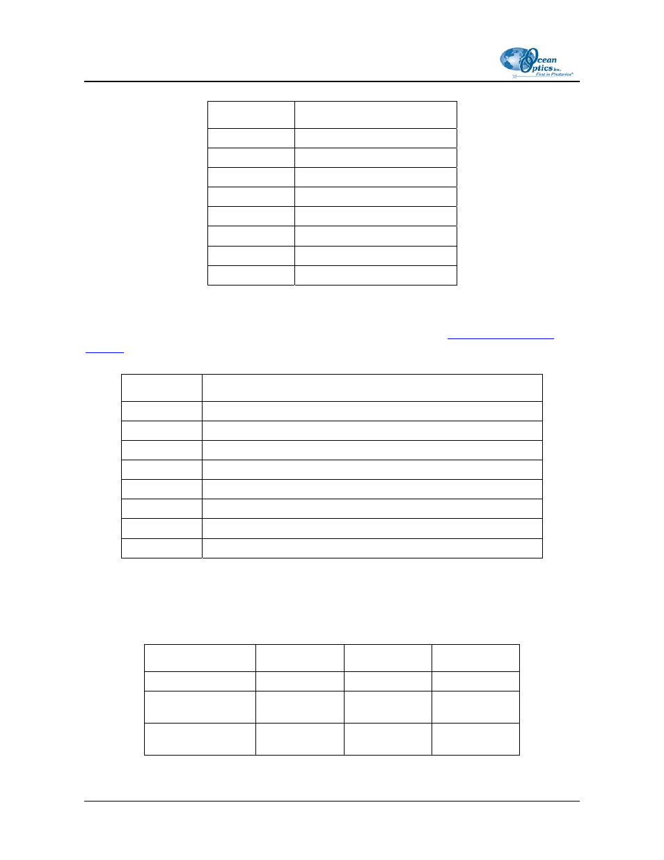
Table 1. PC2000-PC104 Programming Registers
Port Address
PC2000-PC104 Register Description
base + 0
Master Clock Counter Port (base frequency is 8 MHz)
base + 1
Continuous Strobe Counter Port (base frequency is 976 Hz)
base + 2
Integration Clock Counter port (base frequency is 976 Hz)
base + 3
N/A
base + 4
Command port (output only)
base + 5
Software Trigger Digital Input port (bit 3 only)
base + 6
Read Spectral Data (WORD Access)
base + 7
Channel rotation command port
Counter Ports (Base – Base +2) Description
Output frequency of counter is base frequency divided by the 16bit value written to this port. Limits
for the various counters along with the corresponding counter value are provided below.
Counter Min Typical
Max
Master Clock
4Mhz
2
4Mhz
2
Continuous Strobe
2.048ms period
2
Integration Clock
3.072ms period
3
8
000-00000-000-05-0704