Circuit board connectors pinout information – Ocean Optics Breakout Box User Manual
Page 6
HR4-BREAKOUT Installation and Operation Instructions
Pin # Function
Input/Output
Description
19
SPI Clock
Output
SPI clock signal for communication to other SPI peripherals
20
Continuous
Strobe
Output
TTL output signal used to pulse a strobe – Divided down
from the master clock signal
21
SPI Chip
Select
Output
SPI Chip/Device Select signal for communication to other
SPI peripherals
22
GPIO (6)
Input/Output
General purpose software-programmable, digital
input/output (channel number)
23
Analog In
(0–5V)
Input
13-bit low power, analog-to-digital input with a 0–5V range
24
Analog Out
(0–5V)
Output
9-bit programmable output voltage with a 0–5V range
25 Lamp
Enable
Output
TTL signal driven Active HIGH when the Lamp Enable
command is sent to the spectrometer
26 GPIO
(7) Input/Output
General purpose software-programmable, digital
input/output (channel number)
27 Ground
Input/Output
Ground
28 GPIO
(8) Input/Output
General purpose software-programmable, digital
input/output (channel number)
29
Ground
Input/Output
Ground
30 GPIO
(9) Input/Output
General purpose software-programmable, digital
input/output (channel number)
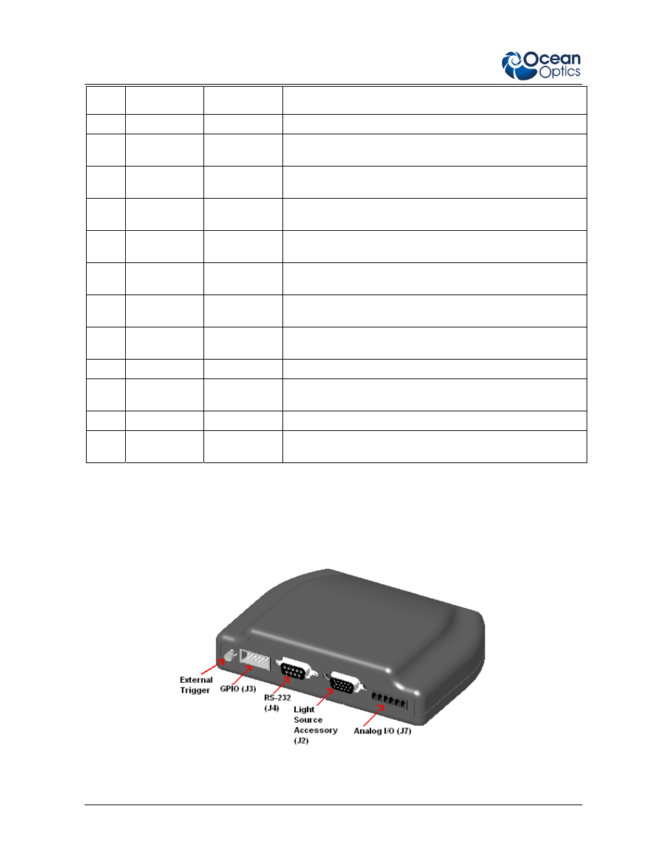
Circuit Board Connectors Pinout Information
The following tables list pinout information for the J2, J3, J4, J5, J6, and J7 connectors on the
breakout box circuit board.
6
212-00000-000-01-1108