Tr2 control signals – Ocean Optics TR2 Engineering Note User Manual
Page 3
TR2 Information Engineering Note
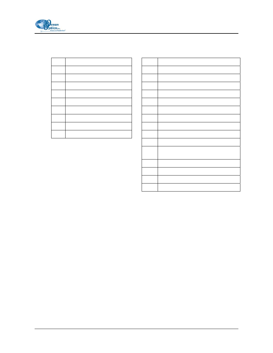
Table 2: S2000-H1 Header Pins (Analog)
Table 3: S2000-H2 Header Pins (Digital)
1
Analog Channel 0
D
N/C
2
Analog Channel 1
C
A/D Trigger
3
Analog Channel 2
B
Software Trigger In (D3)
4
Analog Channel 3
A
Trigger Mode Select (S1)
5
Analog Channel 4
1
GND
6 GND
2 +5
VDC
7 Reserved
3 F
Clock
8
Analog Channel 7
4
Readout Gate
9
Analog Channel 6
5
Reserved
10
Analog Channel 5
6
Temperature (optional)
7 Read
Enable
8
Trigger Mode Select/Strobe Enable
(S0)
9
Single Strobe Out
10
Continuous Strobe Out
11
Integration
Clock
12
Master
Clock
TR2 Control Signals
It is possible to drive the control signals (Toggle Up/Down and Reset) directly. These signals are 5V
TTL Active LOW signals that are pulled HIGH on the TR2 board.
To change the current set point, drive the Reset signal LOW and then pulse the Toggle Up or Toggle
Down LOW. Each falling edge of the Toggle Up/Down signal will drive the set point one position in
the desired direction. Once the desired set point is reached, drive (or release) the Toggle Up/Down
signals HIGH and then drive (or release) the Reset signal HIGH. The Toggle Up/Down signals are de-
bounced on each TR2 and the minimum pulse width is 100ns. There is no maximum pulse width.
To change the nonvolatile power-up set point, hold the Toggle Up/Down signal LOW while the Reset
signal is driven (or released) HIGH. This writes the current wiper setting to the nonvolatile memory
location that is read from upon power-up of the unit.
209-0000-000-04-0704
3