Pin out – Ocean Optics TR2 Engineering Note User Manual
Page 2
TR2 Information Engineering Note
Pin Out
The TR2 interfaces to the S2000 using the H1 & H2 connectors. The pin-out for these signals is show
below. In addition, the TR2 has a J3 connector that communicates the various temperature signals. Its
pin-out is shown in Table 1 below.
When Multiple S2000-TR2 assemblies are stacked together, several signals in the J3 connector must
be connected among all of the TR2 boards in the stack. The Table 1 below defines these signals. In
this condition, the display will only show the actual and set-point temperatures from a single unit.
Typically, this unit is the Master Spectrometer Channel.
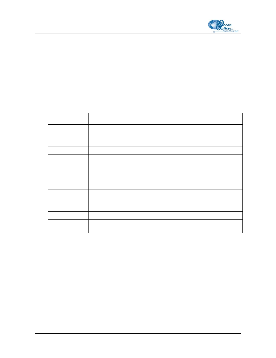
Table 1: J3 Definition
Pin Signal Name Connections
Description
1 N/C
No
Connect
2
VTEMP
From one TR2
(Master)
Analog signal of the current temperature. Scaling is
100mv/
o
C
3
Reset
All
Reset signal for TR2—Active Low
4
VSET
From one TR2
(Master)
Set-point temperature signal to be displayed when
pushbutton is depressed. Scaling is 100mv/
o
C)
5 Ground All
+5V
Ground
6
Vdisplay
From one TR2
(Master)
Analog Signal that is displayed. Scaling is 100mv/
o
C
7
Toggle Down All
Clock signal to toggle the set-point down one increment—
Active Low
8 N/C
No
Connect
9 Ground All
+5V
Ground
10
Toggle Up
All
Clock signal to toggle the set-point up one increment—
Active Low
2
209-00000-000-04-0704