4 install the wiring, 5 adjust the levels & scale factors – Crown Audio IQ-P.I.P.-SMT User Manual
Page 22
Page 22
IQ P.I.P.–SMT
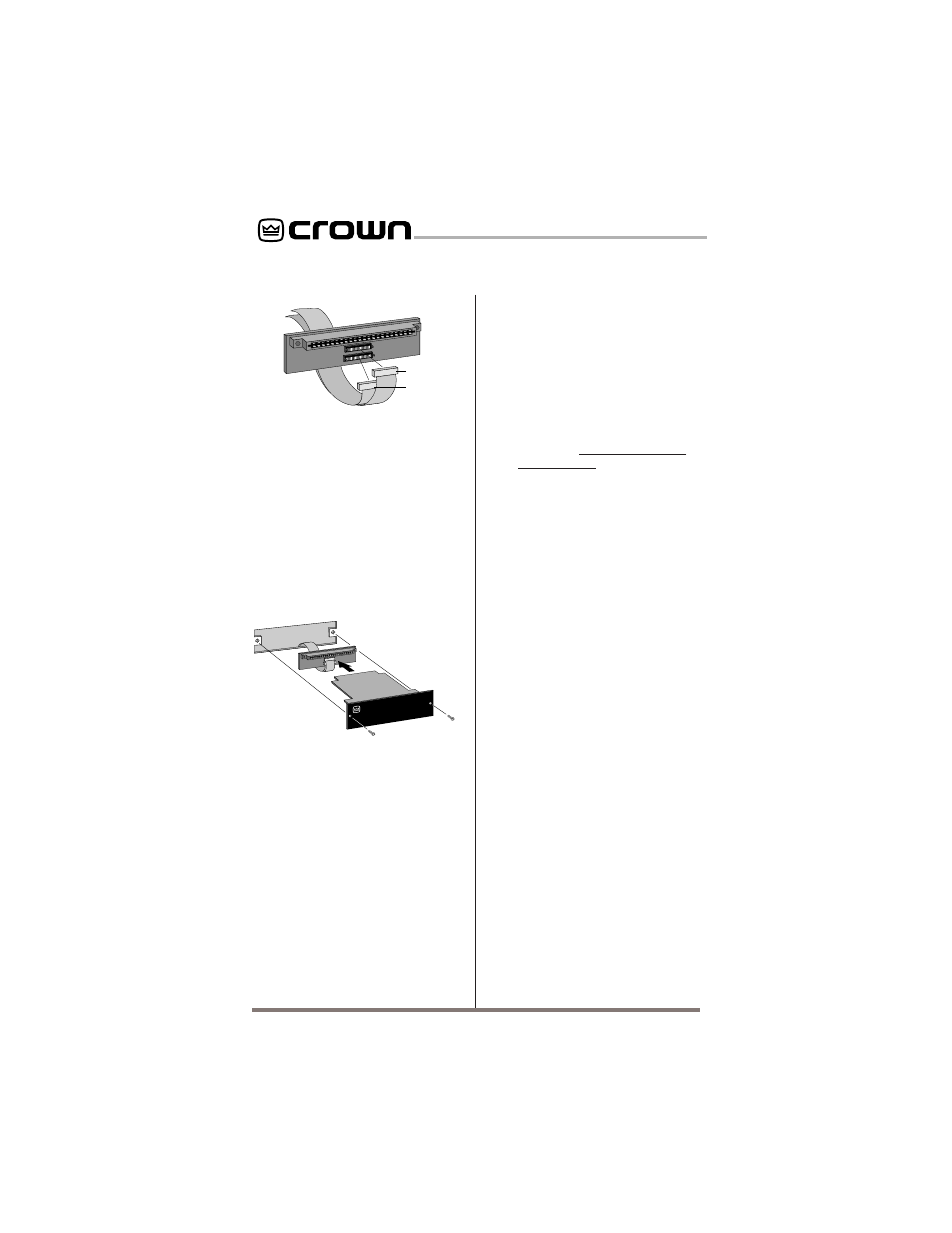
P.I.P.
MODULE
BACK PANEL
OF PIP2
AMPLIFIER
PIP2 CONNECTOR
BOARD
Fig. 4.7 Installation into a PIP2
Amplifier
cables should extend below
the
PIP2 input adapter.
Next, insert the edge con-
nector of the
IQ–P.I.P.–SMT
into the
PIP2 input adapter
(see Figure 4.7) and insert
the assembly into the
P.I.P.
opening in the back of the
amplifier.
4.4 Install the Wiring
11.
Connect the
IQ–P.I.P.–SMT
to the
IQ System via the
Crown Bus.
See Section 4.6
for full instructions.
12.
Connect the audio signal
wiring
to the
IQ–P.I.P.–SMT.
This includes the XLR input
wiring and, if desired, the
phone jack daisy chain wir-
ing. See Section 4.7 for full in-
structions.
13.
Reconnect amplifier to the
AC receptacle.
4.5 Adjust the Levels & Scale
Factors
14.
Turn the level controls of
the amplifier to their full or
maximum setting.
This is re-
quired by the
IQ–P.I.P.–SMT.
If needed, use the software-
controlled input attenuators
on the
IQ–P.I.P.–SMT to re-
duce the audio levels.
15.
Configure the amplifier
scale factors.
(Standard
P.I.P.-compatible amplifiers
only—the scale factors for
PIP2-compatible amplifiers
are set automatically.) It is
necessary to configure soft-
ware scale factors in the mi-
croprocessor of the
IQ–P.I.P.–SMT in order for it to
properly interpret the output
signal level of the amplifier
model in which it is installed.
This is easily done by con-
necting a host computer to
the
IQ–P.I.P.–SMT via an IQ
interface and the Crown Bus
and running the appropriate
software (see the IQ software
User’s Manual for details).
The software will prompt you
for the amplifier model and
send the appropriate scale
factors to the
P.I.P. The scale
factor values are listed in Fig-
ure 4.8 along with the set-
tings of jumpers JP4 and JP5.
Note: Since it is possible to
configure one channel of a
A
B
B
A
18 PIN (B)
20 PIN (A)
Q43528-1
FROM AMPLIFIER
Fig. 4.6 PIP2 Input Adapter
Connection
10.
Tighten the two
P.I.P.
mounting screws
until the
P.I.P. is secured to the ampli-
fier back panel.