2 circuit theory, Page 30 com-tech power amplifiers reference manual, Fig. 5.1 circuit block diagram – Crown Audio Com-Tech "10 Series" User Manual
Page 30: Only one channel shown, Output, Input
Page 30
Com-Tech Power Amplifiers
Reference Manual
FAULT
ONLY ONE CHANNEL SHOWN
NPN HI
OUTPUT
STAGE
NPN L
O
W
OUTPUT
STAGE
PNP L
O
W
OUTPUT
STAGE
PNP HI
OUTPUT
STAGE
+
OUTPUT
+Vcc
–Vcc
TRANSLATOR
LV
A
LV
A
+Vcc
–Vcc
BIAS
CURRENT
LIMIT
TRANSLATOR
BALANCE
INPUT STAGE
P.I.P.
BALANCED
INPUT
VARIABLE
GAIN STAGE
ERROR
AMP
DISPLAY
BIAS
BRIDGE
BALANCE
+Vcc
–Vcc
POWER
SUPPLY
CONTROL
DC
/L
F
TIMER
POWER
SUPPLY
+Vcc
–Vcc
ODEP
A
B
A
(ODEP)
B
(ODEP)
D
E
(DISPLAY)
D
C
(DISPLAY)
E
HS
TEMP
C
(ODEP)
+24
–24
ENABLE
BARRIER
BLOCK
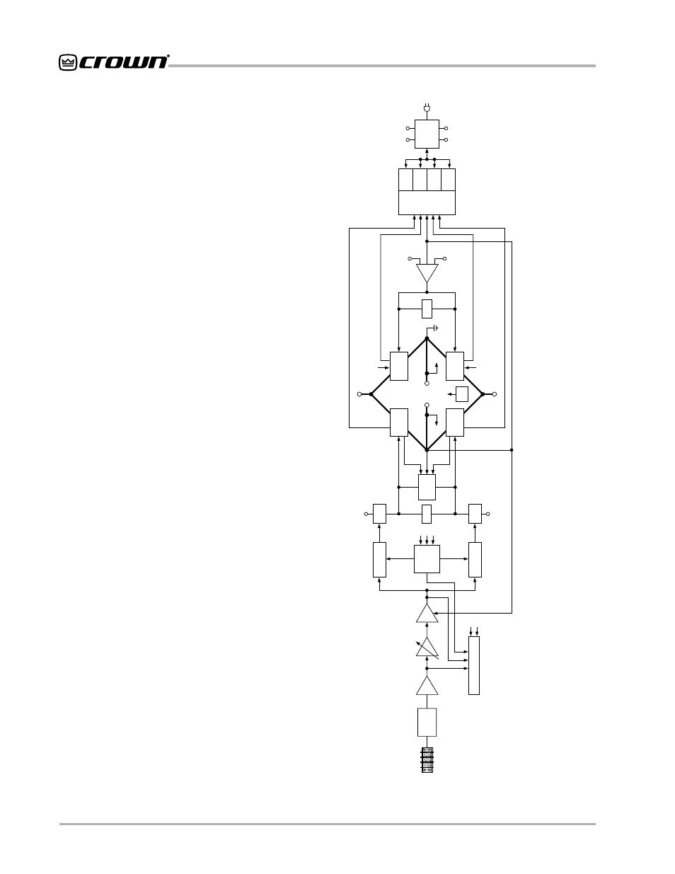
Fig. 5.1 Circuit Block
Diagram
5.2 Circuit Theory
Each channel is powered by its own power transformer
winding. Both channels share a common low-voltage
supply. The secondary output of the power transformer
is full-wave rectified and is filtered by a large computer
grade capacitor. A thermal switch embedded in the
power transformer protects it from overheating.
The low-voltage winding in the power transformer is rec-
tified to generate an unregulated 24 volts. Monolithic
regulators provide a regulated ±15 volts.
5.2.1 Dual Operation
For simplicity, the discussion of Dual operation will refer
to one channel only. Mono operation will be discussed
in Sections 5.2.2 and 5.2.3. Please refer to the block
diagram in Figure 5.1.
The signal at the PIP barrier block passes directly into
the balanced input stage. The balanced input stage
causes balanced to single-ended conversion using a
difference amplifier. Next the variable gain stage ampli-
fies or attenuates the signal. The gain of this stage is set
by the position of the input sensitivity switch and the
back panel Input Attenuation control. The error amp
amplifies the difference between the output signal and
the input signal from the gain pot, and drives the volt-
age translator stage.
From the error amp, the voltage translator stage chan-
nels the signal to the Last Voltage Amplifiers (LVAs), de-
pending on the signal polarity. The +LVA and the –LVA,
with their push-pull effect through the bias servo, and
drive the fully complementary output stage.
The bias servo is thermally coupled to the heat sink,
and sets the quiescent bias current in the output stage
to lower the distortion in the crossover region of the out-
put signal.
With the voltage swing provided by the LVAs, the signal
then gains current amplification through the Darlington
emitter-follower output stage.
The bridge-balanced circuit receives a signal from the
output of the amplifier and detects the difference be-
tween it and the signal at the Vcc supply. The bridge-
balanced circuit then develops a voltage to drive the
bridge-balanced output stage. This results in the Vcc
supply having exactly one half of the output voltage
added to the quiescent voltage.