Crown Audio Com-Tech "10 Series" User Manual
Page 19
Page 19
Com-Tech Power Amplifiers
Reference Manual
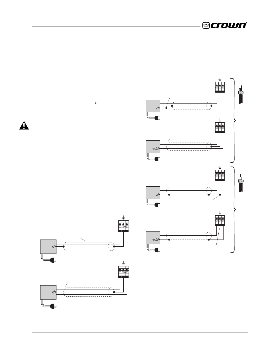
Fig. 3.8 Balanced Input Wiring
Fig. 3.9 Unbalanced Input Wiring
T
win-lead shielded cable
INPUT
2-wire line cord
(or battery power)
Output
Floating
source
Shield connected
to ground terminal
3-wire grounded line cord
(or other ground connection)
Shield not connected
at this end
Grounded
source
3-wire grounded line cord
(or other ground connection)
Input ground
terminal not used
Grounded
source
Single-conductor coax
or twisted pair
+
Output
+
2-wire line cord
(or battery power)
Output
Floating
source
Shield connected to both
negative (–) and ground
input terminals
+
Output
+
+
–
INPUT
+
–
INPUT
+
–
INPUT
+
–
+
–
INPUT
INPUT
2-wire line cord
(or battery power)
Note: If two or more channels with
the same input ground reference
are driven from the same
floating source, connect
only one shield to the
source chassis.
Floating
source
–
+
3-wire grounded line cord
(or other ground connection)
Output
Shield not connected
at this end
Grounded
source
–
+
Output
+
–
To select Parallel-Mono mode, turn off the amplifier and
slide the dual/mono switch to the PARALLEL MONO
(left) position. Connect the input signal to Channel 1
only. The Channel 2 input jack and Input Attenuation
control are bypassed in this mode, so they should not
be used.
Connect the load to the Channel 1 output as shown in
Figure 3.7 (top and bottom illustrations). The positive
lead from the load connects to the positive (+) terminal
of Channel 1, and the negative (or ground) lead from
the load connects to the ground ( ) terminal of Channel
1. Finally, install a jumper wire of at least 14 gauge be-
tween the positive (+) terminals of both channels.*
CAUTION: When Parallel-Mono wiring is installed, do
NOT operate in Dual or Bridge-Mono mode until the
wiring is removed (especially the jumper wire). Fail-
ure to do so will result in high distortion and exces-
sive heating.
3.3.2 Audio Input Connection
The balanced inputs have a nominal impedance of 20 k
ohms (10 k ohms unbalanced) and will accept the line-
level output of most devices. The factory-installed PIP2-
BB provides a balanced three-terminal input barrier
block for each channel (see Figure 2.2). Optional PIP
modules like the
PIP2-FXQ, etc., can provide female
XLR connectors, phone jacks and phono (RCA) con-
nectors. Various PIPs are also available which provide
a wide range of input signal processing features (see
Section 8).
Proper input wiring depends on two factors: (1) whether
the input signals are balanced or unbalanced, and (2)
whether the signal source floats or has a ground refer-
ence. The following illustrations provide examples of
recommended connection techniques for each type of
signal source. (See Figures 3.8 and 3.9.)
S O L V I N G I N P U T P R O B L E M S
Sometimes large subsonic (sub-audible) frequencies
are present in the input signal. These can damage loud-
speakers or step-down transformers by overloading or
overheating them. To attenuate such frequencies, place
a capacitor in series with the input signal line. The graph
in Figure 3.11 shows some capacitor values and how
they affect frequency response. Use only low-leakage
capacitors.