4 advanced features and options – Crown Audio CDi Series User Manual
Page 8
page 14
CDi Series Power Amplifiers
Operation Manual
CDi Series Power Amplifiers
Operation Manual
page 15
4 Advanced Features and Options
Figure 4.1
DC Protection
NOTE: For detailed information about these Crown
amplifier features, please consult the Crown
Amplifier Application Guide, available on the
Crown website at www.crownaudio.com.
4.1 Protection Systems
Your Crown amplifier provides extensive protection and
diagnostic capabilities, including output current limiting,
microprocessor-controlled DC protection, and special
thermal protection for the unit’s transformers and output
devices.
4.1.1 Output Current Limiting
Output Current Limiting circuitry protects the amplifier
output stage from damage caused by short-circuit loads.
4.1.2 DC Protection
DC Protection shuts down the amplifier in the event of an
output DC offset exceeding 2V. In the majority of cases, DC
protection is indicative of a faulty amplifier channel, and will
be accompanied by an illuminated red Clip LED, even with
no input connected and level controls set at minimum
(Figure 4.1). If this is the case, contact your dealer or service
center.
4.1.3 Thermal Protection
The Thermal Protection circuit will activate if the internal
heatsink temperature exceeds proper operating tempera-
tures (176°F, 80°C). When the heatsink temperature has
fallen to a safe level, this protection circuit will automati cally
be reset. Principal causes of thermal protection are:
1) Inadequate ventilation of the equipment rack
2) Incorrect load impedance
3) Output cable short circuit
4) Blocked air vent
5) Heatsinks in need of cleaning
6) Cooling fan failure.
The cause of your amplifier’s thermal protection state should
be determined and corrected as soon as possible. Without
correction, the Thermal Protection circuit will typically
reactivate.
4.1.4 Non-Touch Cover
Located over the amplifier output terminals, this included
accessory provides a shock-proof cover for the output
ter minals.
1. Remove the screw holding the cover onto the amplifier
back panel, and remove the cover. Keep the screw.
2. The cover has two tabs A and B (Figure 4.2). Insert tab A
into the slot just to the left of the output terminals (Fig ure
4.3).
3. Put the screw through tab B, and screw it into the hole
just to the right of the output terminals (Figure 4.3).
4.1.5 Attenuator Security Covers
The included attenuator security covers (Figure 4.4) can
replace the existing level-control knobs so that the
ampli fier output level cannot be changed. The knobs snap
into the front panel.
Tab A
Tab B
Non-touch cover
Figure 4.2 Interior of Non-Touch Cover
Tab A
Tab B
Non-touch cover
Figure 4.3 Cover Placement
Over Output Terminals
Figure 4.4 Attenuator Security Cover
4 Advanced Features and Options
(continued)
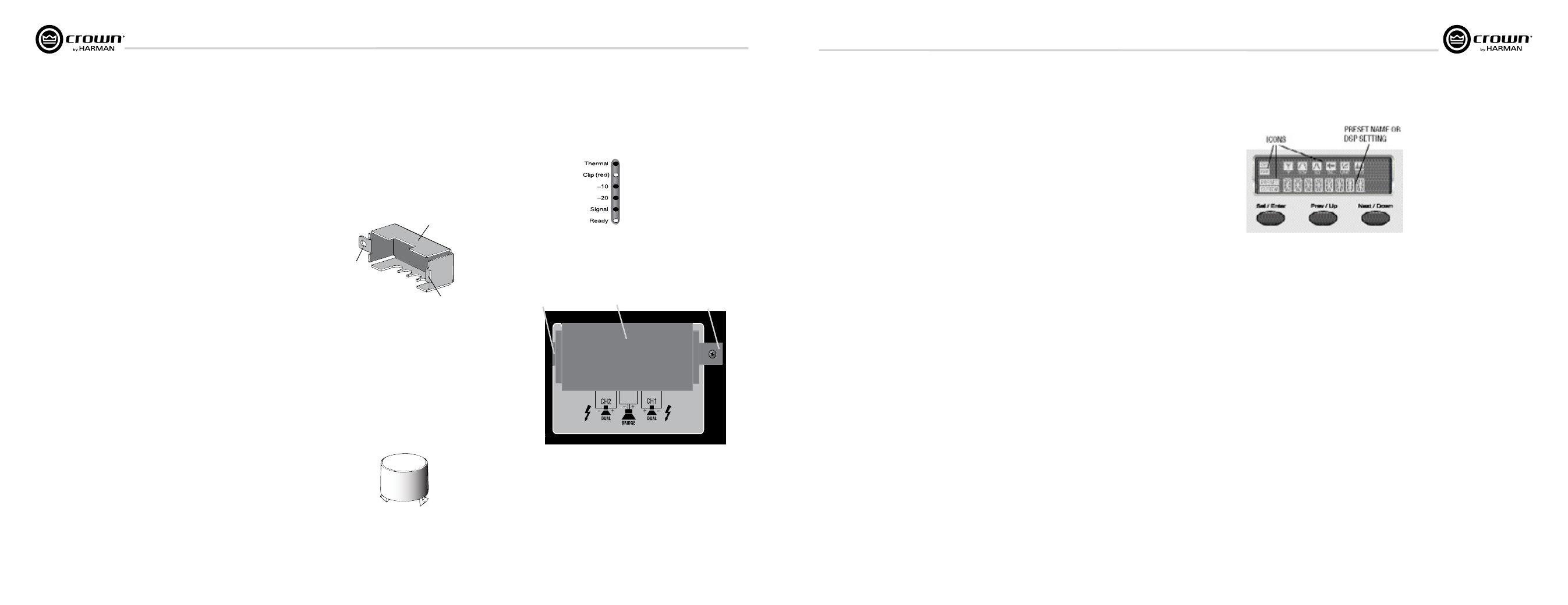
Figure 4.5 LCD Screen and Menu
Navigation Buttons
Figure 4.6 Menu Tree
4.1.6 DSP Presets and Processes
OVERVIEW
Figure 4.5 shows the LCD screen and the three Menu
navigation buttons: Sel/Enter, Prev/Up and Next/Down.
These buttons let you step through the menu items
displayed on the screen.
You can configure USER PRESETS with your own set tings.
When you power off and back on, your settings will be as
they were when you shut off the amplifier. However, if you
recall a user preset, all its DSP will be off– unless you had
saved the preset using System Architect software (a free
download from www.harman pro.com). Any custom settings
can’t be saved by the front panel display, only by System
Architect software.
The ICONS in the display illuminate to show which DSP
functions are currently in use for each preset.
You can select the presets with the LCD screen and Menu
navigation buttons.
From the front panel, you can change settings for several of
the amplifier’s DSP processes: cross overs, EQ bypass,
delay, 70V mode, and output lim iting. The ICONS in the
display illuminate to show which DSP functions are
currently applied.
When you power-on the amplifier for the first time, the LCD
screen displays DSP OFF (no DSP is applied). Subsequent
power-ons display the preset that was active when you shut
off the amplifier.
Figure 4.6 shows the Menu Tree, which is the navi gation
path of options in the Menu. Later in this manual is a table
that shows how to access various presets and DSP
processes
.
On the next page is a description of each block in the Menu Tree.