2 setup – Crown Audio CDi Series User Manual
Page 4
page 6
CDi Series Power Amplifiers
Operation Manual
CDi Series Power Amplifiers
Operation Manual
page 7
2 Setup
2.1 Unpack Your Amplifier
Please unpack and inspect your amplifier for
any damage that may have occurred during
transit. If damage is found, notify the
transpor tation company immediately. Only you
can ini tiate a claim for shipping damage. Crown
will be happy to help as needed. Save the
shipping carton as evidence of damage for the
shipper’s inspection.
We also recommend that you save all packing
materials so you will have them if you ever need
to transport the unit. Never ship the unit
without the factory pack.
YOU WILL NEED (not supplied):
• Input wiring cables
• Output wiring cables
• Rack for mounting amplifier (or a stable
sur face for stacking)
WARNINg: Before you start to set up
your amplifier, make sure you read and
observe the Important Safety Instruc-
tions found at the beginning of this
manual.
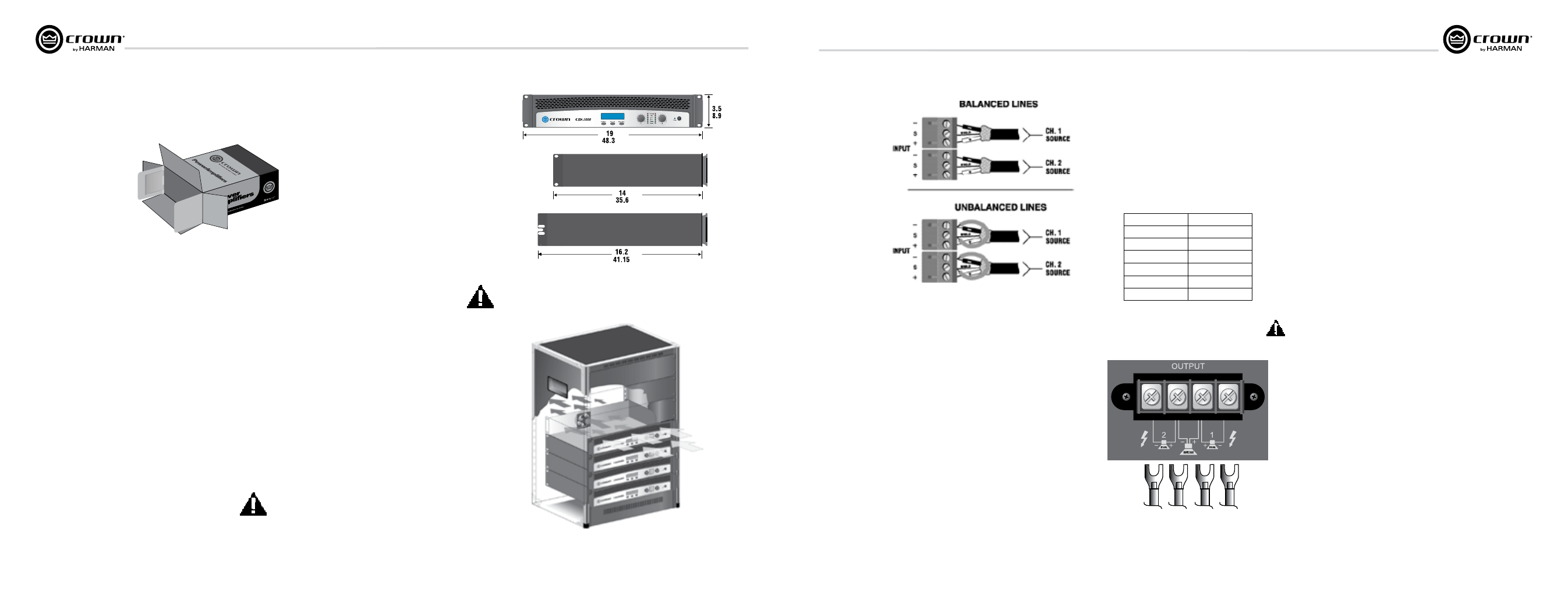
Figure 2.2
Airflow
Figure 2.1
Dimensions
2.2 Install Your Amplifier
CAUTION: Before you begin, make sure
your amplifier is disconnected from the
power source, with the power switch in
the “off” position and all level controls
turned completely down (counterclock-
wise).
Use a standard 19-inch (48.3 cm) equipment
rack (EIA RS-310B). See Figure 2.1 for ampli fier
dimensions.
You may also stack amps without using a
cabinet.
NOTE: When transporting, amplifiers should be
supported at both front and back.
2.3 Ensure Proper Cooling
When using an equipment rack, mount units
directly on top of each other. Close any open
spaces in rack with blank panels. DO NOT block
front or rear air vents. The back of the rack
should be open.
Figure 2.2 illustrates standard amplifier airflow.
CDi 6000
CDi 1000
CDi 2000
CDi 4000
In.
In.
In.
In.
cm
cm
cm
cm
Figure 2.3 Input Connector Phoenix Wiring,
Bal anced (Top) and Unbalanced (Bottom)
2.4 Choose Input Wire
and Connectors
Crown recommends using pre-built or professionally wired
balanced line (two-conductor plus shield), 22-24 gauge
cables and connectors. At the amplifier inputs, use
Phoe nix-style connectors (see Figure 2.3).
Unbalanced lines may be used, but may result in hum or RF
noise over long cable runs.
NOTE: Custom wiring should only be performed by
qualified personnel.
2 Setup
(continued)
Figure 2.4 Barrier Strip Output Wiring
2.5 Choose Output Wire and Connectors
Crown recommends using pre-built or professionally
wired, high-quality, two-conductor, heavy gauge
speaker wire and connectors. You can use spade lugs or
bare wire for your output connectors (Figure 2.4). To
prevent the possibility of short-circuits, wrap or
other wise insulate exposed loudspeaker cable
connectors.
Using the guidelines below, select the appropriate size
of wire based on the distance from amplifier to speaker.
Distance
Wire Size
up to 25 ft.
16 AWG
26-40 ft.
14 AWG
41-60 ft.
12 AWG
61-100 ft.
10 AWG
101-150 ft.
8 AWG
151-250 ft.
6 AWG
CAUTION: Never use shielded cable for output
wiring.