3 installation, 1 mounting, 2 cooling – Crown Audio Macro-Tech Series (600, 1200 & 2400) User Manual
Page 10
Macro-Tech 600/1200/2400 Power Amplifiers
Page 10
Reference Manual
If the air supply is unusually dusty, you might want to
pre-filter it using commercial furnace filters to prevent
rapid loading of the unit’s own air filter. When needed,
the unit’s filter can be cleaned with mild dish detergent
and water (see Section 4.5).
BLOWER
(OPTION 2)
BLOWER
(OPTION 1)
AIR
FLOW
FRONT
OF
RACK
DOOR
AIR
FLOW
EQUIPMENT
RACK
(SIDE VIEW)
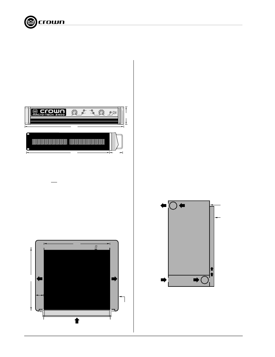
Fig. 3.3 Proper Air Flow in a Rack Cabinet
3 Installation
3.1 Mounting
Macro-Tech amplifiers are designed for standard
19-inch (48.3-cm) rack mounting and “stack” mounting
without a cabinet. For more efficient cooling and extra
support in a rack, it is recommended that units be
stacked directly on top of each other.
Important: If the unit will be transported, it should also
be securely supported at the back of the rack.
Fig. 3.2 Top View of a Rack-Mounted Unit
AIR
FLOW
AIR FLOW
AMPLIFIER
(TOP VIEW)
RACK
CABINET
16 in
40.6 cm
2 in
(5 cm)
MIN.
IMPORTANT: Be sure rear of amplifier
is securely mounted to rack.
17 in
43.2 cm
AIR
FLOW
3.2 Cooling
NEVER block the side or front air vents. Macro-Tech
amplifiers do not need to be mounted with space be-
tween them. If you must leave open spaces in a rack
for any reason, close them with blank panels to prevent
air from recycling into the front of other amplifiers. Allow
at least 35 cubic feet (1 cubic meter) per minute per
unit for the Macro-Tech
600 and 1200, and at least 45
cubic feet (1.3 cubic meters) per minute per unit for the
Macro-Tech 2400. Additional air flow may be required
when driving low impedance loads at consistently high
output levels. Refer to Section 7 for detailed information
on thermal dissipation.
Fig. 3.1 Mounting Dimensions
19 in
48.3 cm
16 in
40.6 cm
3.5 in
8.9 cm
2.5 in
6.35 cm
SIDE VIEW
LEVEL
LEVEL
ON
OFF
30
27
24
21
18
15
12
9
6
3
0
ENABLE
CH1
CH2
ODEP
30
27
24
21
9
6
3
0
SIGNAL / IOC
18
15
12
When mounting the amplifier in a rack, the side walls of
the rack should be at least 2 inches (5 cm) away from
the chassis as shown in Figure 3.2.
Tip:
An easy way to verify adequate cooling is to ob-
serve the ODEP indicators while the amplifier is operat-
ing under worst-case conditions. If the indicators dim,
additional cooling is recommended.
If your rack has a front door that could block air flow to
the amplifier’s air intakes, you must provide adequate
air flow by installing a grille in the door or by pressuriz-
ing the air behind the door. Wire grilles are recom-
mended over perforated panels because they tend to
cause less air restriction. A good choice for pressuriz-
ing the air behind a rack cabinet door is to mount a
“squirrel cage” blower inside the rack (Option 1 below).
At the bottom of the rack, mount the blower so it blows
outside air into the space between the door and in front
of the amplifiers, pressurizing the “chimney” behind the
door. This blower should not blow air into or take air out
of the space behind the amplifiers. For racks without a
door, you can evacuate the rack by mounting the
blower at the top of the rack so that air inside the cabi-
net is drawn out the back (Option 2 below).