4 advanced features, Continued) – Crown Audio CTs Series (Multi-Channel USP_CN) User Manual
Page 12
Operation Manual
CTs Multi-Channel Power Amplifiers
page 22
page 23
CTs Multi-Channel Power Amplifiers
Operation Manual
NOTE: For more information about these Crown
amplifier features, please visit the Crown
web site at www.crownaudio.com.
4.2 Protection Systems
Your Crown amplifier provides extensive protection and
diagnostic capabilities, including thermal level control,
fault indicators, automatic high-pass filtering, DC pro tect,
AC under-voltage and over-voltage protection, inrush
limiting, and variable-speed fans.
4.2.1 Thermal Level Control (TLC)
If an amplifier channel starts to overheat, the TLC circuit
will engage that channel’s input compressor. By
com pressing the input, the amplifier will not generate as
much heat and will have a chance to cool down. The
degree of compression is proportional to the amount of
overheating. If the channel becomes too hot for safe
operation even after full TLC limiting, the channel will
shut off, and the Thermal Indicator for that channel will
flash brightly to alert the user that a state of thermal stress
or overload has cause the channel to shut down.
4.2.2 Fault
If an amplifier channel requires service, the correspond-
ing Fault indicator will illuminate to alert the user of this
condition. If this occurs, return the amplifier to the Crown
factory or to an authorized Crown service center.
4.2.3 Fault Isolation Topology (FIT)
Crown’s new FIT (Fault Isolation Topology) design
iso lates channel-specific faults, and prevents them from
affecting remaining channels. If a CTs multi-channel amp
is powering multiple zones, and a channel fails, the other
zones continue to operate. FIT makes the CTs 4200USP/
CN and CTs 8200USP/CN the most trustworthy multi-
channel amplifiers in the business!
4.2.4 High-Pass Filter
A fixed 35-Hz (70-Hz in CTs 4200USP/CN) high-pass
fil ter per channel pair is automatically inserted when the
mode switch is set to either of the constant-voltage
set tings. The high-pass filter corner frequency can be set
to 70 Hz, or bypassed, with a service option.
4.2.5 AC Under-Voltage and Over-Voltage
Protection
If the AC line voltage varies out of an acceptable range,
the amplifier’s power supply turns off and the blue Power
LED flashes. The LED will continue to flash until the
power has been cycled. Figure 4.4 provides voltage lim its
for all amplifier AC voltage configurations. Also, the
amplifier must be run within the specified mains
fre quency requirements (indicated on the amplifier’s back
panel label). If you are unsure of the output voltage of
your AC mains, consult your electrician.
Models
Under-Voltage
Limit
Over-Voltage
Limit
100VAC
90VAC
110VAC
120 VAC units
108VAC
132VAC
220V/230V/
240V units
198VAC
264VAC
4.2.6 Power Fuse
A fuse protects the amplifier from excessive AC current
draw.
4.2.7 Inrush Limiting
A soft-start circuit in the power supply minimizes the
amplifier’s current draw during power-on.
4.2.8 Variable-speed Fans
Continuously variable speed fans direct the airflow
through the amplifier for cooling.
4.2.9 Switching Power Supply
Crown’s new Switching Power Supply minimizes the
amplifier’s weight.
Typical non-switching power supplies require large,
heavy transformers in order to produce the required
power at the output stage. These transformers must be
large to absorb the substantial waste that occurs when
operating at 50 to 60 Hz (standard AC supplied by the
power company).
By contrast, switching power supplies can operate with a
much smaller (and lighter) transformer because they first
convert the AC up to a much higher frequency, thereby
reducing waste.
The power supply is voltage-specific, allowing use in
regions using 120V/60Hz, 220V/50Hz, 230V/50Hz,
240V/50Hz, and 100V/50Hz AC mains.
4.2.10 Mode Switch
Each consecutive pair of channels has one four-position
switch that selects the amplifier’s mode of operation. The
switch positions are:
• Dual mode for 4 or 8 ohm operation.
• Dual mode for 70V constant-voltage operation.
• Bridge-Mono mode for 8 or 16 ohm operation.
• Bridge-Mono mode for 100V constant-voltage
oper ation.
Be sure to turn off the amplifier before changing
the Mode-switch setting.
4.2.11 Bridge Mode Indicator
This yellow LED indicates when the amplifier’s mode
switch is set to the Bridge position. Each consecutive pair
of channels has one Bridge LED.
4 Advanced Features
(continued)
Figure 4.4 AC Under-Voltage and
Over-Voltage Limits for Various Amplifier
Models
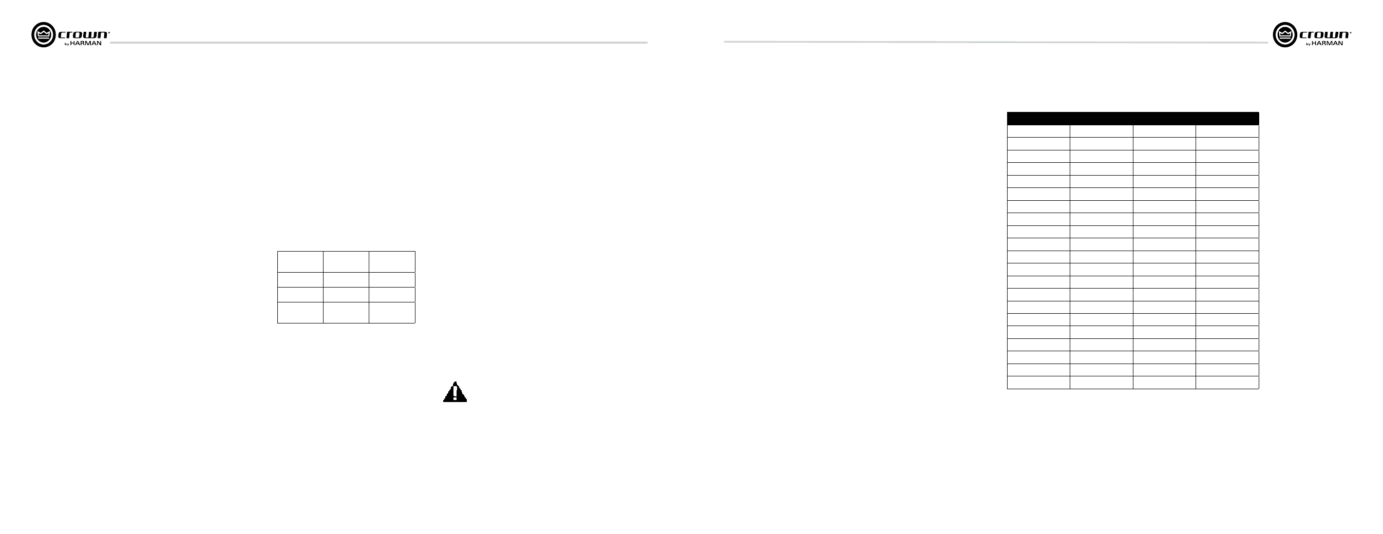
4.2.12 Channel Level Control
The signal level for each input can be attenu ated
accurately by adjusting the 21-step Level
Control (see Section 2.5). Figure 4.5 shows the
amount of attenuation in dB for each detent.
Note: Attenuation per detent varies with
operat ing mode since gain varies with operating
mode. Attenuation amounts shown may vary
±6%.
Detent
4/8 Ohm
70V
100V
0 (full CCW)
-68.31
-72.90
-71.02
1
-67.54
-72.06
-70.26
2
-32.23
-36.61
-34.90
3
-25.46
-29.74
-28.00
4
-21.83
-25.87
-24.22
5
-19.23
-23.20
-21.58
6
-17.12
-20.94
-19.40
7
-15.36
-19.02
-17.53
8
-13.76
-17.22
-15.79
9
-12.28
-15.53
-14.20
10
-10.84
-13.90
-12.62
11
-9.51
-12.32
-11.16
12
-8.28
-10.87
-9.81
13
-7.09
-9.45
-8.45
14
-6.30
-8.11
-7.22
15
-4.92
-6.70
-5.94
16
-3.82
-5.26
-4.63
17
-2.62
-3.70
-3.21
18
-1.35
-1.90
-1.66
19
-0.01
-0.01
-0.01
20 (full CW)
0.00
0.00
0.00
ATTENUATION in dB
Figure 4.5 Level-control Attenuation per Detent
4 Advanced Features
(continued)