Installation 2 – Crown Audio P.I.P.-ISO User Manual
Page 7
P.I.P.-ISO
Page 7
A
B
B
A
18 PIN (B)
20 PIN (A)
Q43528-1
FROM AMPLIFIER
P.I.P.
MODULE
BACK PANEL
OF PIP2
AMPLIFIER
PIP2 CONNECTOR
BOARD
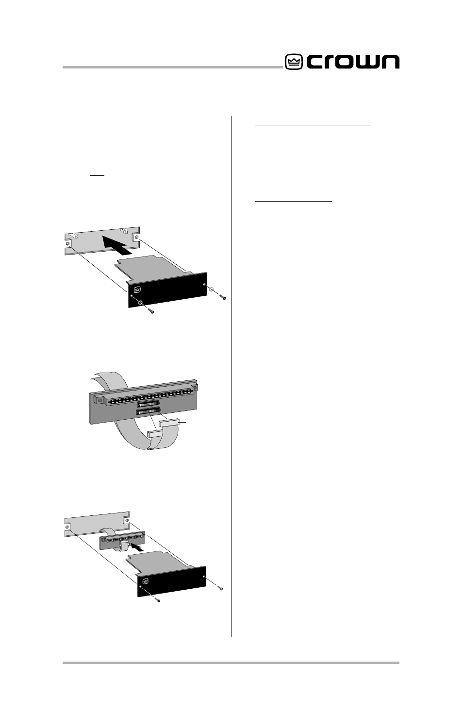
Fig. 3.3 PIP2 Input Adapter
Connection
Fig. 3.4 Installation into a
PIP2 Amplifier
P.I.P.
MODULE
BACK PANEL
OF AMPLIFIER
Fig. 3.2 Installation into a
Standard P.I.P. Amplifier
involve disconnecting the
P.I.P.
from a
PIP2
input adapter (see
Figures 3.3 and 3.4). If a
PIP2
input adapter is already present,
do not remove the ribbon cables
from the adapter. Otherwise you
will have to reconnect them in the
next step.
3.
Standard P.I.P. Amplifiers
: Align
the edges of the
P.I.P.–ISO
in the
P.I.P.
card rails and firmly push
the unit in until it is seated against
the mounting bracket (see
Figure 3.2).
PIP2 Amplifiers:
(Requires a
PIP2
input adaptor. Crown part
number Q43528-1.) Connect
the
PIP2
input adapter to the two
input cables of the amplifier (see
Figure 3.3). Notice that the
PIP2
input adapter should be
positioned with the
P.I.P.
edge
connector on top and facing
away from the amplifier. The 20
pin cable (A) is connected first
then the 18 pin cable (B) is
connected. Both ribbon cables
should extend below the
PIP2
input adapter.
Next, insert the edge connector
of the
P.I.P.–ISO
into the
PIP2
input adapter (see Figure 3.4)
and insert the assembly into the
P.I.P.
opening in the back of the
amplifier.
4. Secure the
P.I.P.–ISO
with the
two screws and lock washers
provided. (The lock washers are
important because they bond
the
P.I.P.
to the chassis ground
of the amplifier.)
5. Connect input and output wiring.
6. Plug in the amplifier and turn it
on. Adjust its level controls to a
desired setting.
Do not tamper with the circuitry.
Circuit changes made by unautho-
rized personnel, or unauthorized
circuit modifications are not al-
lowed.