Installation 1, 3 installation, 1 installation procedures – Crown Audio P.I.P.-ISO User Manual
Page 6
P.I.P.-ISO
Page 6
3 Installation
The
P.I.P.-ISO
provides input iso-
lation with any
P.I.P.
-compatible
amplifier but it will only provide
output isolation with an amplifier
that has been ISO-MODIFIED.
Only a Crown-authorized service
technician should attempt to
modify an amplifier. Instructions
for iso-modifying
Com-Tech
ampli-
fiers are included in each ISO-
MOD KIT.
Before installing this
P.I.P.
module,
you’ll want to adjust its subsonic/
bass filters to best serve your
needs.
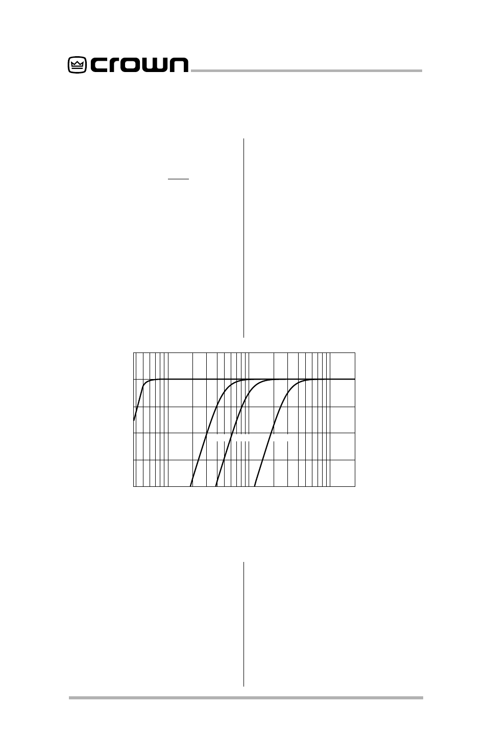
This is easily accomplished with the
four-position sliding switch located
at either side of the
P.I.P.-ISO
(see
Figure 2.2 and 2.3). The switch on
the left controls the filter for Channel
2 and the switch on the right con-
trols the filter for Channel 1. Each
switch is clearly labelled (Flat, 50
Hz, 100 Hz, 300 Hz). Figure 3.1
shows the low-frequency response
through the P.I.P.-ISO for each filter
position.
Note: The RFI filter is always on.
3.1 Installation Procedures
You may need a phillips screw-
driver to remove the existing
P.I.P.
module or panel from your amplifier.
CAUTION:
CAUTION:
CAUTION:
CAUTION:
CAUTION: Before connecting this
or any
P.I.P.
to your amplifier, it is
important to turn its level controls
down, turn it off and remove the AC
power. Don’t touch the circuitry.
Even though the amplifier is off,
there could still be enough energy
remaining to cause electric shock.
1. Turn down the level controls (full
counterclockwise), turn off the
amplifier and unplug it from the
AC power source.
2. Remove the existing
P.I.P.
module or panel (two screws).
For
PIP2
amplifiers, this may
10
100
1 K
FREQUENCY (Hz)
dB
0
–6
–12
–18
FLAT
50 Hz
100 Hz
300 Hz
Fig. 3.1 Subsonic/Bass Filter Settings