3B Scientific Teltron Tube Holder D User Manual
Page 4
3B Scientific GmbH • Rudorffweg 8 • 21031 Hamburg • Germany • www.3bscientific.com
Subject to technical amendments
© Copyright 2010 3B Scientific GmbH
3. Technical data
Dimensions: 230x175x320
mm
3
approx.
Separation of
holes for coils:
76 mm approx.
Weight:
1.5 kg approx.
4. Operation
4.1 Setting up and removing hot cathode tubes
•
Tubes should not be mounted or removed
unless all power supplies are disconnected.
•
Push the jaw clamp sliders on the stanchion of
the tube holder right back so that the jaws
open.
•
Push the bosses of the tube into the jaws.
•
Push the jaw clamps forward on the stanchions
to secure the tube within the jaws.
•
To remove the tube, push the jaw clamps right
back again and take the tube out of the jaws.
4.2 Setting up the Helmholtz coils (U191051)
•
Place the tube in the holder as described
above.
•
Insert the Helmholtz tubes into the holes with
the connections facing outwards. Push the
sleeves on the rod upwards and insert the rod
at an angle.
•
Push the sleeves into the holes to secure the
coils.
4.3 Setting up the auxiliary coil (U19106)
•
Place the coil on the upper fork.
•
Push the retaining slider over the lip of the
auxiliary coil to secure the coil in place.
4.4 Setting up the optical analogue equipment
(U10172)
•
Insert the aluminium disc with the grating into
the stanchion from behind.
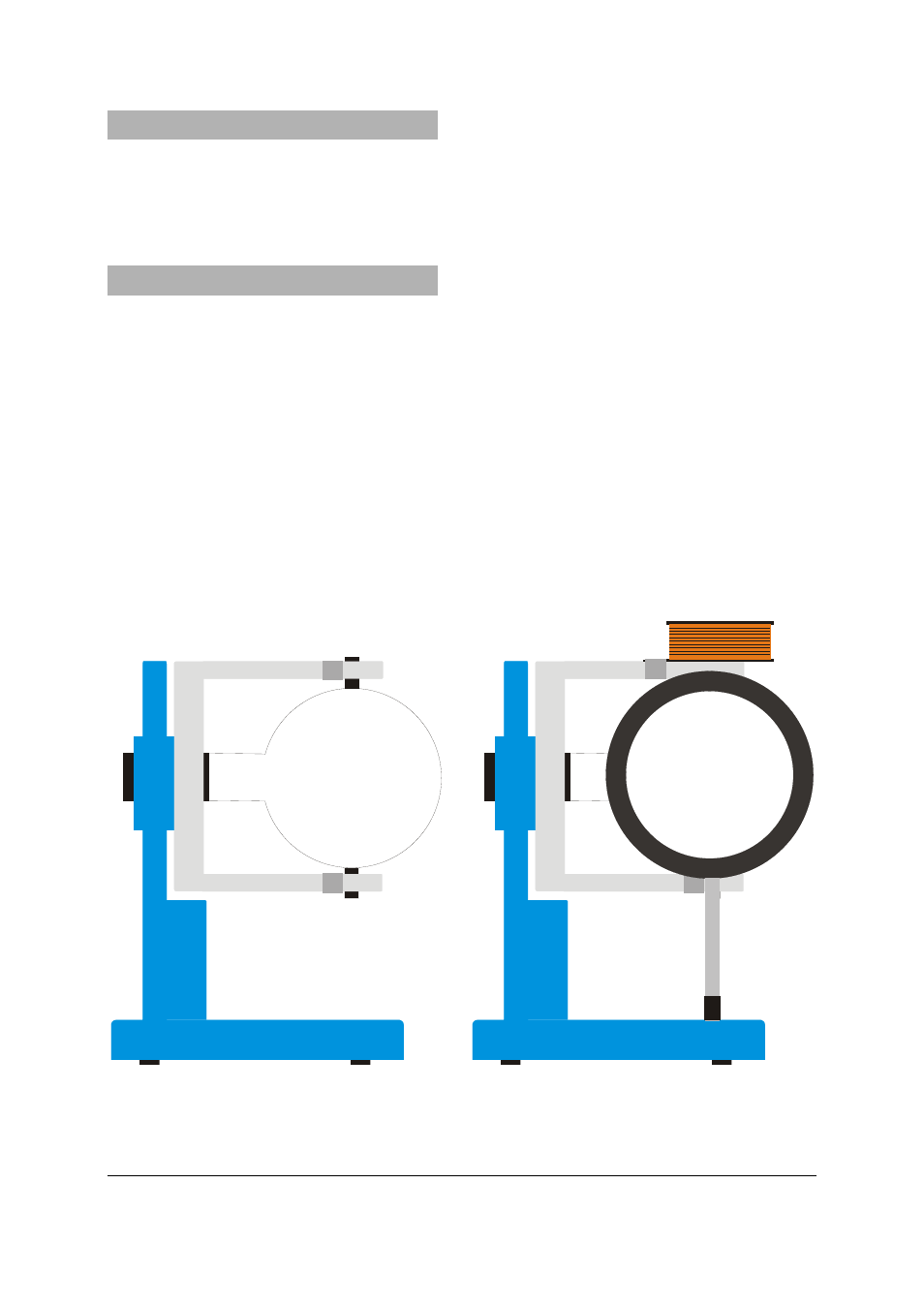
Fig. 1 Setting up a tube (left), a tube, the Helmholtz coils and the auxiliary coil (right)