3B Scientific Light Sensor User Manual
Page 4
3B Scientific GmbH • Rudorffweg 8 • 21031 Hamburg • Germany •
www.3bscientific.com
Subject to technical amendments
© Copyright 2008 3B Scientific GmbH
6. Experimental applications
Investigation of the inverse square law for a point
light source
Properties of polarising filters
Demonstration of the flickering effect of alternat-
ing current for fluorescent lamps
Measurement of solar energy
Studies of reflection
Measurements of illuminance at work-stations and
personal areas
Relationship between light intensity and growth of
plants
7. Sample experiment
Investigation of the inverse square law for a
point light source
Apparatus needed:
1 3B NETlog
TM
U11300
1 3B NETlab
TM
U11310
1 Light sensor
U11364
1 Experimental lamp, halogen
U17140
1 Transformer 12 V, 60 VA
U13900-230
(alternative to the variable transformer shown in
Fig. 1)
1 Barrel foot
U8611200
1 Vertical ruler, 1 m
U8401560
2 Universal clamps
U13255
•
Set up the experiment as shown in Fig. 1.
•
On the 3B NETlab
TM
, open the application pro-
gram (template) for the experiment with the
light sensor.
•
Lay the ruler horizontally, and fix the experi-
mental lamp at the 15 cm mark using one of
the universal clamps.
•
Define this point as distance zero, 0.
•
Mount the light sensor on the ruler using the
other universal clamp.
•
Connect the electric cables to the experimental
set-up and switch on.
•
Start the template program, select “manual
input”, and measure the light intensity at the
first point, a distance of 5 cm in front of the
experimental lamp.
•
Increase the distance in steps of 5 cm up to the
70 cm mark (a distance of 55 cm from the ex-
perimental lamp), and record the correspond-
ing light intensities in the 3B NETlab
TM
(Fig. 2).
•
Generate the data curve using the “Fit” func-
tion.
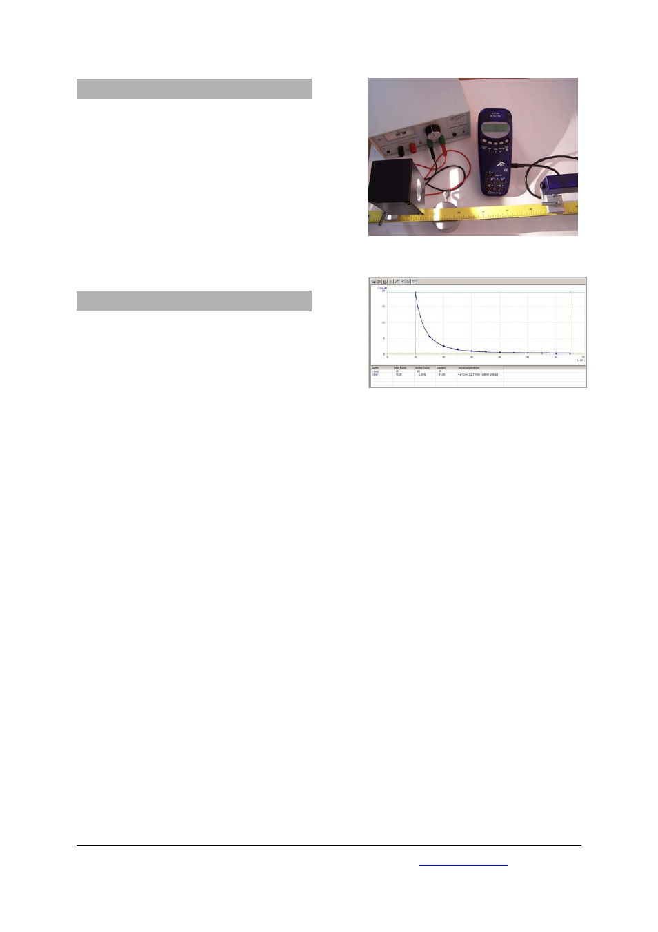
Fig. 1 Investigation of the inverse square law for a point
light source
Fig. 2 Plot of the data points from the inverse square
law experiment on the monitor screen of the 3B
NETlab
TM
(U11310)