Rear panel operations – dbx 1046 User Manual
Page 10
6
Rear panel operations
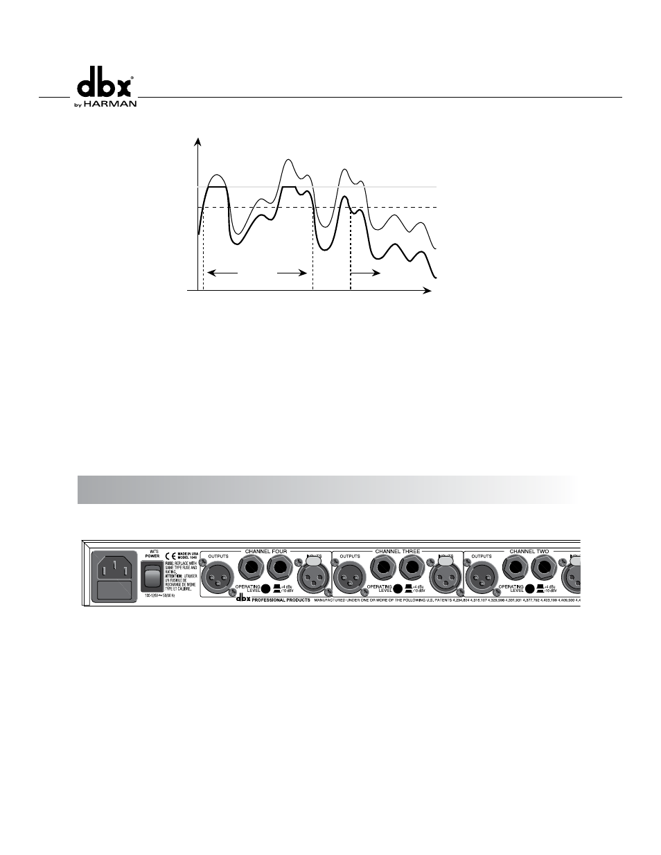
Time
Output Signal
Input Signal
Output Signal
Intelligent Predictive Limiting™
Release Time
Attack Time
}
2 dB Typically
Figure 3: Protective Action of the PeakStopPlus™ Limiter
Stereo Couple Switch - These switches change the 1046 from four independent compressors into two stereo
compressors. In stereo mode, Channel 1 is the master and Channel 2 is its slave, and Channel 3 is the master
and channel 4 is its slave. Each of the Channel 2 and 4 controls and switch functions will be overriden and
controlled by the Channel 1 and 3 controls and switches, respectively, except for the I/O Meter and Bypass
switches. Also, Channel 2’s and 4’s Compressor Threshold, and PeakStopPlus™ Threshold meters will be disabled,
while these slave channels’ Gain Reduction meters will indicate the amount of gain reduction occurring, as
on their masters’ Gain Reduction Meters. All 4 channels have equal precedence as far as signal processing is
concerned. The dbx 1046 uses True RMS Power Summing™, an extremely accurate and musical way to combine
detector outputs in a stereo situation. The switch will light to indicate that the 1046 is in the Stereo Couple
mode.
Rear Panel Operations
Rear Panel
FUSE: T 300mA L 250V
30
AC Power Receptacle - Use the supplied AC cable to connect the unit to AC power. The AC receptacle includes
an integral pull-out fuse drawer which contains two fuses; the active fuse and a spare fuse. Replace the fuse
with the same type and rating only.as indicated on the rear panel.
Audio Inputs - Each channel features both XLR and 1/4” TRS electronically balanced inputs. Inputs may be used
in a balanced or unbalanced configuration. Note that the XLR and 1/4’ inputs may NOT be used simultaneously.