Operating controls – dbx 1046 User Manual
Page 6
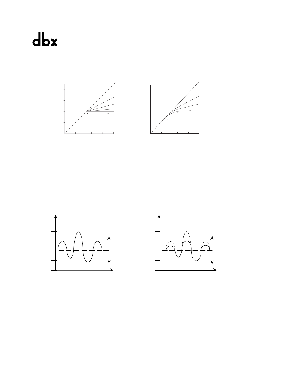
the compressed region. This smooth transition greatly reduces compression artifacts and allows higher
compression ratios while still maintaining the natural characteristics of the signal. The switch lights to
indicate OverEasy® processing is enabled. When conventional hard knee processing is desired, disable
the OverEasy® function. See Figure 1 below.
Figure 1: Hard Knee Compression Curve and OverEasy® Compression Curve.
Compressor Ratio Control
- This control selects the ratio between input and the output levels for
signals above the level set by the COMPRESSION THRESHOLD control. It is adjustable between 1:1
and ∞:1. Note, when OverEasy® processing is selected, the ratio transitions smoothly from the linear to
the compressed region. As the signal exceeds the threshold, the ratio approaches the ratio set by the
COMPRESSOR RATIO control.
Figure 2 shows the effect of 2:1 compression on a signal as it rises above and falls below the threshold.
Below the threshold the signal is not affected. Above the threshold, the output signal increases by only
half of the increase (in dB) of the input signal level. In other words, with a 2 dB increase in input level,
the output increases by only 1 dB, hence the 2:1 compression ratio.
Figure 2: Compression Effect on Signal Level with a 2:1 Ratio at a -20 dBu Threshold
Input/Output Level Meter
- This 8-stage meter directly reads the input and output levels when the rear-
panel OPERATING LEVEL SWITCH is in the +4 dBu position. In the -10 dBV position, the input signal
is boosted by 11.8 dB (the difference between +4 dBu and -10 dBV) to convert a semi-pro -10 dBV level
signal to the professional +4 dBu internal level of the 1046, while the output signal is attenuated by 11.8
dB to convert back to a -10 dBV level. Since the meter is calibrated for +4 dBu operation, it reads about
12 dB higher than the actual input and output signal levels when the OPERATING LEVEL SWITCH is
set to -10 dBV.
Input/Output Meter Switch
- This switch selects the signal for metering by the INPUT/OUTPUT LEVEL
-40
-30
-20
-10
0
10
Time
Signal Level (dBu)
Below Threshold
Above Threshold
Input Signal
Output Signal
-40
-30
-20
-10
0
10
Time
Signal Level (dBu)
Below Threshold
Above Threshold
Input Signal
4
Operating controls
®
1:1
2:1
4:1
:1
−15
−10
−5
0
+5
+15
+20
+10
INPUT LEVEL (dB)
OUTPUT LEVEL (dB)
−15 −10 −5
0
+5
+15 +20
+10
RED
Below Threshold
Above Threshold
OverEasy Range
G
R
E
EN
AM
BE
R
-15
-10
-5
0
+5
+15
+20
+10
INPUT LEVEL (dB)
OUTPUT LEVEL (dB)
-15 -10
-5
0
+5
+15 +20
+10
1:1 Unity
2:1
4:1
:1
20:1
RED
Above Threshold
GREEN
Below Threshold
Rotation Point Threshold