Ironwood Electronics SBT User Manual User Manual
Page 5
4 |
P a g e
S B T
. d o c , R e v . C , 6 / 2 8 / 2 0 1 2 , V P
Tel: (800) 404-0204
www.ironwoodelectronics.com
5. Turn the compression screw clockwise, until it makes contact with the compression plate and/or the
BGA package.
6. Turn the compression screw further so that BGA balls are compressed on the spring pins to make
contact. When turning becomes hard, full compression is achieved. Internal stops will prevent over
compression when turned by hand.
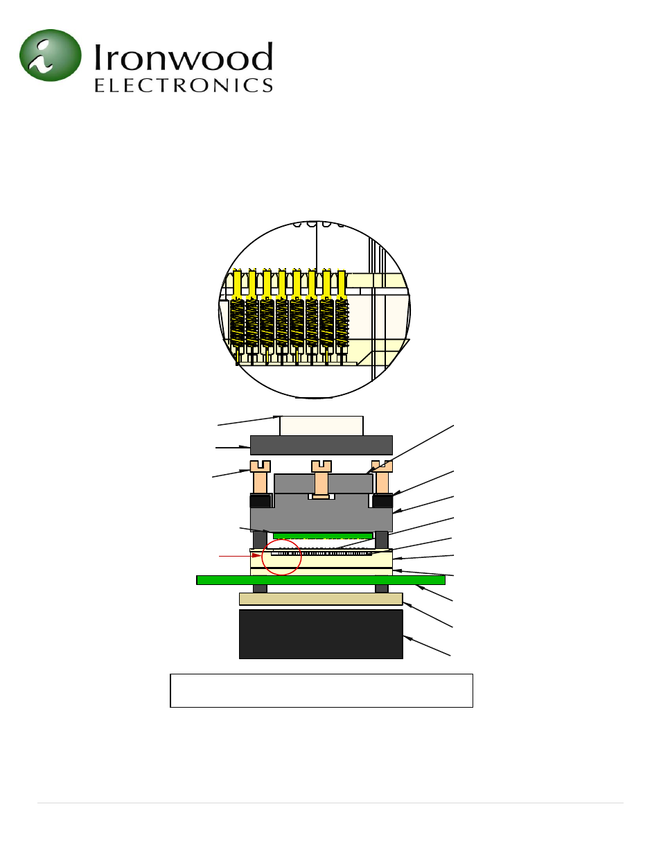
Figure 4: Graphical Illustration of Socket Assembly
De tail
Backing plate
Insulation plate
Target PCB
Bottom pin guide
Middle pin guide
Floating pin guide
Socket base
Mounting screw
Floating
compression
plate
Compression
screw
Swivel lid
Lid shoulder
screw
BGA device
Stamped SBT pin